background image

Communication Protocol 


21 

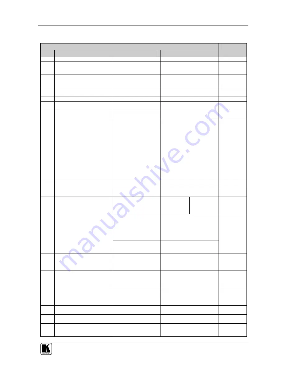
Table 8: Instruction Codes

Note: All values in the table are decimal, unless otherwise stated. 

INSTRUCTION 

DEFINITION FOR SPECIFIC INSTRUCTION 

DESCRIPTION 

INPUT 

OUTPUT


NOTE 

RESET VIDEO 

SWITCH VIDEO 

Set equal to video input 

which is to be switched 

(0 = disconnect) 

Set equal to video output which is 

to be switched  

(0 = to all the outputs) 

2, 15 

SWITCH AUDIO 

Set equal to audio input 

which is to be switched 

(0 = disconnect) 

Set equal to audio output which 

is to be switched 

(0 = to all the outputs) 

STORE VIDEO STATUS 

Set as SETUP # 

0 - to store  

1 - to delete 

2, 3, 15 

RECALL VIDEO STATUS 

Set as SETUP # 

2, 3, 15 

REQUEST STATUS OF A 

VIDEO OUTPUT 

Set as SETUP # 

Equal to output number whose 

status is reqd 

4, 3 

REQUEST STATUS OF AN 

AUDIO OUTPUT 

Set as SETUP # 

Equal to output number whose  

status is reqd 

4, 3 

VIS SOURCE 

Set as input # when 

OUTPUT byte = 6; 

OR  

set as output # when 

OUTPUT byte = 7; 

OR 

set as blank period  

(in steps of 25ms) when  

OUTPUT byte = 32;  

OR  

set = 0. ***** 


0 - No VIS (immediate) 

1 - Input # 1 

2 - External digital sync 

3 - External analog sync 

4 - Dynamic sync 

5 - Inter-machine sync 

6 - Input # (INPUT byte) 

7 - Output #(INPUT byte) 

8 - User-defined sync 

32 - RGBHV seamless switching 

64 - Set for delayed switch 

65 - Execute delayed switch 

66 - Cancel delayed switch 

setting 

2, 5, 17, 18 


0 - audio-follow-video 

1 - audio breakaway 

BREAKAWAY SETTING 

0 - FOLLOW mode 

1 - Normal mode 

15 

0 - for video 


0 - CV 

1 - YC 

2 - YUV 

3 - RGBS 

4 - SDI 

5 - CV+YC 

6 - VGA scaler 

7 - DVI 

1 - for audio 

O0=0 – Unbalanced audio 

O0=1 – Balanced audio 

O1=0 – Digital audio 

O1=1 – Analog audio 

O4=0, O3=0, O2=0-Mono 

O4=0, O3=0,O2=1-Stereo 

VIDEO / AUDIO TYPE SETTING 

2 - for VGA and DVI 

1 - 640X480 

2 - 800X600 

3 - 1024X768 


10 

REQUEST VIS SETTING 

Set as SETUP #, or  

set to 126 or 127 to 

request if machine has this 

function 

0 - VIS source  

1 - Input # or output # of source 

2 - Vertical sync freq (Hz) 

3, 4, 6, 7 

11 

REQUEST BREAKAWAY 

SETTING 

Set as SETUP #, or  

set to 126 or 127 to 

request if machine has this 

function 

0 - Request audio breakaway 

setting 

1 - Request “FOLLOW” setting 

3, 4, 6, 15 

12 

REQUEST VIDEO / AUDIO 

TYPE SETTING 

Set as SETUP #, or  

set to 126 or 127 to 

request if machine has this 

function 

0 - for video 

1 - for audio 

2 - for VGA 

3, 4, 6 

13 

SET HIGHEST MACHINE 

ADDRESS  

0 - for video 

1 - for audio 

Set equal to highest machine 

address 

14 

REQUEST HIGHEST MACHINE 

ADDRESS 

0 - for video 

1 - for audio 

15 

REQUEST WHETHER SETUP 

IS DEFINED / VALID INPUT IS 

DETECTED 

SETUP #  

or  

Input # 

0 - for checking if setup is defined 

1 - for checking if input is valid 

Summary of Contents for VS-808DS

Page 1: ...Kramer Electronics Ltd USER MANUAL Model VS 808DS 8x8 Video Audio Matrix Switcher Scaler...

Page 2: ...Follow Video Option 15 7 3 2 Setting the Breakaway Option 15 7 4 Confirming Settings 15 7 4 1 Toggling between the At Once and Confirm Modes 16 7 4 2 Confirming a Switching Action 16 7 5 Storing Reca...

Page 3: ...ures 5 Table 2 VS 808DS 8x8 Video Audio Matrix Switcher Scaler Rear Panel Features 6 Table 3 Dipswitch Settings 12 Table 4 Self Address Dipswitch Settings 13 Table 5 Technical Specifications of the VS...

Page 4: ...emote control transmitter including the required batteries and a separate user manual3 and this user manual3 2 Getting Started We recommend that you Unpack the equipment carefully and save the origina...

Page 5: ...KRAMER SIMPLE CREATIVE TECHNOLOGY Getting Started 2 Video Player Video Recorder LCD Display...

Page 6: ...via an external remote IR receiver optional3 and remotely by RS 485 or RS 232 serial commands transmitted by a touch screen system PC or other serial controller Scaled graphics output resolutions VGA...

Page 7: ...KRAMER SIMPLE CREATIVE TECHNOLOGY Your VS 808DS 8x8 Video Audio Matrix Switcher Scaler 4 Figure 1 VS 808DS 8x8 Video Audio Matrix Switcher Scaler Front Panel...

Page 8: ...e inputs an OFF ALL combination disconnects all the outputs 9 TAKE Button Pressing TAKE toggles the mode between the Confirm mode2 and the At Once mode user confirmation per action is unnecessary When...

Page 9: ...Terminal Block Port Pin G is for Ground connection 1 Pins B and A are for RS 485 25 RS 232 DB 9F Port Connects to the PC or the Remote Controller 26 SCALER OUTPUT HD15 Connector Connects to the video...

Page 10: ...Installing on a Rack 7 5 Installing on a Rack This section describes what to do before installing on a rack and how to rack mount...

Page 11: ...CA connectors to up to eight composite video acceptors for example composite video recorders TV and so on 3 Connect a PC and or controller to the RS 232 port see section 6 1 4 Connect3 the SCALER OUT...

Page 12: ...Connecting the VS 808DS 9 Figure 2 Connecting the VS 808DS 8x8 Video Audio Matrix Switcher Scaler...

Page 13: ...onnect the Null modem adapter with a 9 wire flat cable to the RS 232 DB9 port on your PC To connect without using a Null modem adapter Connect the RS 232 DB9 port on your PC to the RS 232 DB9 rear pan...

Page 14: ...ar panel port of the VS 808DS unit Connect the B PIN on the RS 485 rear panel port of the RC 3000 to the B PIN on the RS 485 rear panel port of the VS 808DS unit If shielded twisted pair cable is used...

Page 15: ...witcher and PC OFF disables reply from switcher to PC 6 3 1 Setting the SELF ADDRESS Dipswitches The SELF ADDRESS determines the position of a VS 808DS unit in the sequence specifying which VS 808DS u...

Page 16: ...the controlling device knows that the controlled device has carried out its instructions When an RS 485 connection is used for communication between the Matrix Switcher and the PC dipswitch 8 should...

Page 17: ...ter switching on the power and When simultaneously pressing and holding for 3 seconds the INPUT buttons 1 2 and 3 see section 7 6 7 2 Selecting and Connecting an Output and or Input To switch an input...

Page 18: ...on The audio will follow the video 7 3 2 Setting the Breakaway Option To set the Breakaway option Press either the AUDIO for audio control only or the VIDEO for video control only button If the AUDIO...

Page 19: ...s 7 4 2 Confirming a Switching Action To confirm a switching action in the Confirm mode do the following 1 Press an OUTPUT INPUT combination The corresponding input number that is displayed in the STA...

Page 20: ...Press the RCL button The RCL button blinks 2 Press the appropriate INPUT SELECTOR button the INPUT SELECTOR button corresponding to the setup The memory recalls the stored data from that reference 7 5...

Page 21: ...UT RESOLUTIONS VGA 640 x 480 SVGA 800x600 XGA 1024x768 WXGA 1366x 768 SCALED OUTPUT REFRESH RATE 60Hz MAX OUTPUT LEVEL VIDEO 2 2Vpp CV 0 77Vpp XGA AUDIO 22dBm BANDWIDTH 3dB VIDEO 200MHz AUDIO 100kHz D...

Page 22: ...e of Hex Codes for the Master VS 808DS Table 6 shows the HEX codes for switching the master VS 808DS Table 6 Hex Codes for Switching the Master VS 808DS 8 7 6 5 4 3 2 1 OUT IN 1 IN 2 IN 3 8 7 6 5 IN 4...

Page 23: ...e below INSTRUCTION NO is the value to be set for N5 N0 2nd BYTE Bit 7 Defined as 1 I6 I0 INPUT When switching ie instruction codes 1 and 2 the INPUT 7 bits is set as the input number which is to be s...

Page 24: ...byte 8 User defined sync 32 RGBHV seamless switching 64 Set for delayed switch 65 Execute delayed switch 66 Cancel delayed switch setting 2 5 17 18 0 0 audio follow video 1 audio breakaway 2 8 BREAKAW...

Page 25: ...trast 3 decrease contrast 4 increase brightness 5 decrease brightness 6 increase colour 7 decrease colour 8 increase hue 9 decrease hue 16 increase H phase 17 decrease H phase 18 increase V position 1...

Page 26: ...XTENDED DATA 7 MSBs for INPUT data 7 MSBs for OUTPUT data 20 NOTES on the above table NOTE 1 When the master switcher is reset e g when it is turned on the reset code is sent to the PC If this code is...

Page 27: ...is programmable NOTE 12 Under normal conditions the machine s present status is saved each time a change is made The power down save auto save may be disabled using this code Note that whenever the ma...

Page 28: ...ex you would first send HEX codes 3F 80 85 81 and then send HEX codes 16 83 A9 81 To set the audio gain of output 6 to 10013dec 271Dhex first send HEX codes 3F 80 CE 81 followed by HEX codes 16 86 9D...

Page 29: ...KRAMER SIMPLE CREATIVE TECHNOLOGY 26...

Page 30: ...or the latest information on our products and a list of Kramer distributors visit our Web site www kramerelectronics com where updates to this user manual may be found We welcome your questions commen...

Reviews: