


KRAMER: SIMPLE CREATIVE TECHNOLOGY
Your VP-747T Presentation Switcher Control Panel
6
Table 1: VP-747T Presentation Switcher Control Panel Features
#
Feature
Function
1
LAMP
Button
Toggles the gooseneck lamp ON/OFF
2
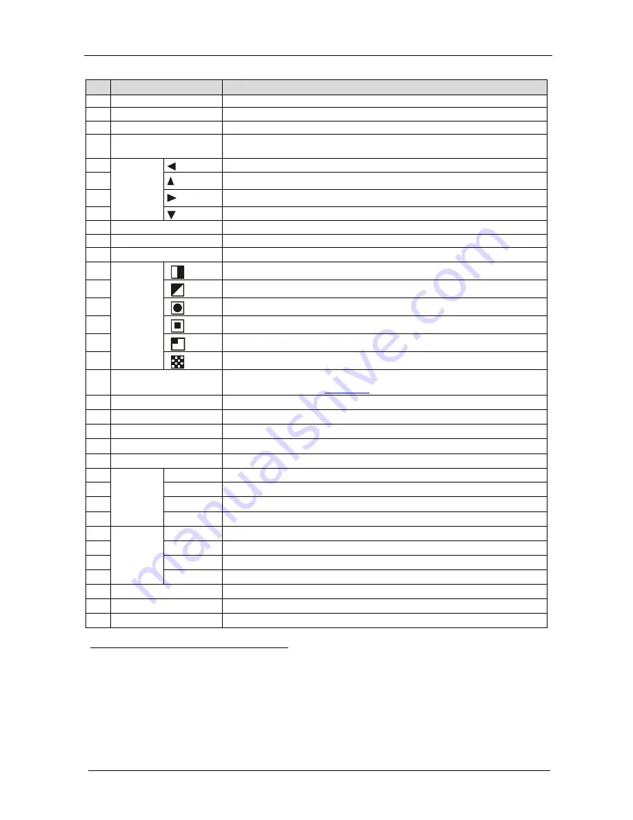
MENU
Button
Displays the OSD Menu screen (or moves to the previous level in the OSD menu)
3
ENTER
Button
Moves to the next level in the OSD menu
4
CONTROLLER ON
Button
Toggles the
VP-747T
Presentation Switcher Control Panel ON/OFF
5
O
S
D
N
A
V
IG
A
T
IO
N
B
ut
to
ns
Toggles within each level 2 command / decreases the range by one step
6
Moves up one step (in the same level) in the OSD menu
7
Toggles within each level 2 command / increases the range by one step
8
Moves down one step (in the same level) in the OSD menu
9
OSD
Button
Activates/deactivates access to the OSD Menu
1
10
FADE
2
Button
Selects a dissolved transition from
the PREVIEW to the PROGRAM output
11
CUT
2
Selects an instantaneous transition from the PREVIEW to the PROGRAM output
Button
12
T
R
A
N
S
IT
IO
N
B
ut
tons
3
5,
Selects a
WIPE
transition effect
13
Selects a
DIAGONAL
transition effect
14
Selects a
CIRCLE
transition effect
15
Selects a
SQUARE
transition effect
16
Selects a
CORNER
transition effect
17
Selects a
CHESSBOARD
transition effect
18
WIPE DIRECTION
Buttons
Choose the direction of the effect
4
: inwards, outwards, “left to right”, “right to
left”, “up” or “down” (see
Section 8.1
19
)
SPEED
Knob
Adjusts the
TAKE
button transition speed
20
TAKE
Button
5
Pressing
TAKE
causes the transition to occur automatically
21
PREVIEW
LED
Lights when the T-bar Controller is directed upwards
22
PREVIEW
LED
Lights when the T-bar Controller is directed downwards
23
T-bar Control Lever
6
Slide to manually implement the effect using the T-bar handle
24
P
R
OGR
A
M
B
ut
to
ns
PIP
Toggles the picture-in-picture function on and off
25
BLANK
Toggles between a blank screen and the selected input
26
FREEZE
Freezes the output video image (toggle)
27
INPUTS
Selects one of the sources: R/P
R
, G/Y/CV, B/P
B
/C, H
S
/C
S
,
V
S
(from 1 to 8)
28
PR
EVI
EW
B
ut
to
ns
PIP
Toggles the picture-in-picture function on and off
29
BLANK
Toggles between a blank screen and the selected input
30
FREEZE
Freezes the output video image (toggle)
31
INPUTS
Selects one of the sources: R/P
R
, G/Y/CV, B/P
B
/C, H
S
/C
S
,
V
S
(from 1 to 8)
32
MACHINE # Button
Pressing selects which MACHINE # is controlled
33
7-segment LED Display
Shows the MACHINE #
34
Lamp Connector
Connects to the gooseneck lamp
1 The LCD is not affected by the OSD setting
2 Only for setting up the unit for the effect. The effect will only occur when the Take button is pressed, or the T-bar is moved
3 Select a specific effect for the transition from the PREVIEW output to the PROGRAM output
4 From where the effect starts
5 The effect is only seen in PROGRAM Mode. The PREVIEW screen will blank during the transition
6 An alternative to using the TAKE button


