background image

Using the VP-437xl 


15 

15 

7.2.4 

The OSD Menu 

Table 6

 defines the OSD menu. 

Table 6: The OSD Menu Features 

Parameter 

Function  

H POSITION 

Set the horizontal position of the OSD (from 0 to 100) 

V POSITION  

Set the vertical position of the OSD (from 0 to 100) 

TIMER 

Set the timeout period in seconds (from 5 to 100) 

BACKGROUND  Set the OSD background between 0 (solid black) and 8 (transparent) 
DISPLAY 

Select

1

7.3 Connecting to the VP-437xl via RS-232 

 between INFO, ON, OFF 

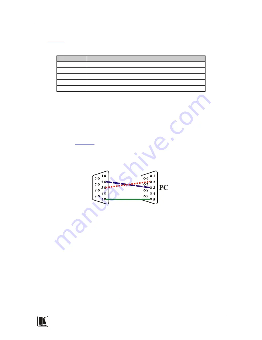
You can connect to the unit via a crossed RS-232 connection, using for 

example, a PC. A crossed cable or null-modem is required as shown in 

method A and B respectively. If a shielded cable is used, connect the shield to 

pin 5. 

Method A

 (

Figure 3

)—Connect the RS-232 9-pin D-sub port on the unit via a 

crossed cable (only pin 

2

 to pin 

3

, pin 

3

 to pin 

2

, and pin 

5

 to pin 

5

 need be 

connected) to the RS-232 9-pin D-sub port on the PC. 

Note:

 There is no need to connect any other pins. 


Figure 3: Crossed Cable RS-232 Connection


Hardware flow control is not required for this unit. In the rare case where a 

controller requires hardware flow control, short pin 1 to 7 and 8, and pin 4 to 

6 on the controller side. 


1 Select the information shown on the screen during operation The information is shown permanently when set to ON; it is 
not shown when set to OFF, and it is shown for a few seconds when set to INFO 

Summary of Contents for VP-437xl

Page 1: ...Kramer Electronics Ltd USER MANUAL Model VP 437xl Presentation Switcher Scaler...

Page 2: ...17 8 Technical Specifications 18 9 RS 232 Communication Protocol 19 Figures Figure 1 VP 437xl Presentation Switcher Scaler 6 Figure 2 Connecting the VP 437xl Presentation Switcher Scaler 11 Figure 3...

Page 3: ...rack ears and Null modem adapter Infrared remote control transmitter This user manual2 2 Getting Started We recommend that you Unpack the equipment carefully and save the original box and packaging ma...

Page 4: ...KRAMER SIMPLE CREATIVE TECHNOLOGY Getting Started 2...

Page 5: ...eo audio outputs Automatically detects and selects the audio source for the HDMI input Default selection is HDMI if this is not present then the machine uses the audio from the analog input Comes with...

Page 6: ...e6 Is backward compatible with DVI Digital Visual Interface and user friendly connector Supports two way communication between the video source such as a DVD player and the digital television enabling...

Page 7: ...nce deterioration in signal quality due to poor matching and elevated noise levels often associated with low quality cables Avoid interference from neighboring electrical appliances and position your...

Page 8: ...KRAMER SIMPLE CREATIVE TECHNOLOGY Your VP 437xl Presentation Switcher Scaler 6 Figure 1 VP 437xl Presentation Switcher Scaler...

Page 9: ...image 1 11 MENU Button Displays the OSD menu see section 7 2 12 ENTER Button Press to accept changes change the SETUP parameters 2 7 1 1 and to auto adjust the image when not within the OSD menu see s...

Page 10: ...acceptor 32 VGA 15 pin HD Connector Connect to a VGA acceptor 33 AUDIO IN Unbalanced Stereo Terminal Block Connectors HDMI Connect to the analog audio HDMI source from 1 to 2 VGA Connect to the analo...

Page 11: ...Installing the VP 437xl in a Rack 9 5 Installing the VP 437xl in a Rack This section provides instructions for rack mounting the unit...

Page 12: ...ignals to the AUDIO IN terminal block connectors as required not shown in Figure 2 7 Connect the RGBHV VIDEO OUTPUT BNC connectors to an RGBHV acceptor for example an RGBHV display 8 Connect the HDMI...

Page 13: ...Connecting the VP 437xl Presentation Switcher Scaler 11 Figure 2 Connecting the VP 437xl Presentation Switcher Scaler...

Page 14: ...PANEL LOCK buttons buttons 2 7 1 1 The Auto Adjust Feature The auto adjust feature3 automatically centers the image on the screen when pressing the ENTER front panel button or the OK button on the re...

Page 15: ...80I50 1080i 50Hz XGA 1024x768 1080P50 1080p 50Hz SXGA 1280x1024 1280x800 1280x800 UXGA 1600x1200 WSXGA 1680x1050 480I 480i WUXGA 1920x1200 480P 480p WSXGA 1440x900 720P60 720p 50Hz AUDIO See section 7...

Page 16: ...Select the audio delay time OFF 40ms 110ms and 150ms SOUND Select the sound options ON MUTE MUTE FOLLOWS Select the action that will be followed by mute INDEPENDENT5 FREEZE BLANK FREEZE BLANK6 HDMI AU...

Page 17: ...equired as shown in method A and B respectively If a shielded cable is used connect the shield to pin 5 Method A Figure 3 Connect the RS 232 9 pin D sub port on the unit via a crossed cable only pin 2...

Page 18: ...the D sub connector Because the null modem adapter which already includes the flow control jumpering described in Method A above only requires pins 2 3 and 5 to be connected you are free to decide wh...

Page 19: ...und and enabling the audio output AV Select the composite video input YC Select the s Video input COMP1 Select the component video 1 input COMP2 Select the component video 2 input PC Select the UXGA i...

Page 20: ...1400x1050 OUTPUT REFRESH RATE 60Hz for computer graphics resolutions 50 60Hz for HDTV resolutions CONTROLS CV YC component 1 component 2 VGA HDMI 1 HDMI 2 input selector buttons blank mute freeze but...

Page 21: ...ASCII code 0x0D LF 1 Line Feed ASCII code 0x0A Set and get command Set Command Type in Y Control_Type Function Param CR 2 Reply Z Control_Type Function Param CR LF Get Command Type in Y Control_Type F...

Page 22: ...control 0 14 N A INFO button on remote control 0 15 N A UP button on remote control 0 16 N A NATIVE button on remote control 0 17 N A LEFT button on remote control 0 18 N A OK button on remote control...

Page 23: ...D Setting V Position 1 Set 2 Get 43 0 100 OSD Timeout 1 Set 2 Get 44 0 8 OSD Background 1 Set 2 Get 50 0 3 NR Noise Reduction 0 Off 1 Low 2 Mid 3 High 1 Set 2 Get 51 0 3 Audio delay 0 Off 1 40ms 2 110...

Page 24: ...576i 12 576p 13 720p50 14 1080i50 15 1080p50 16 WXGA 17 WSXGA 18 WUXGA 19 1280x800 20 WXGA 1440X900 21 SXGA 1400X1050 3 Set 23 1 Factory Reset 6 Set 7 Get 0 0 1 Power 0 Power Down 1 Power On 6 Set 7...

Page 25: ...fnature ii Product modification orfailureto followinstructions supplied with theproduct iii Repairorattemptedrepairby anyonenot authorized byKramer iv Anyshipment oftheproduct claims must bepresentedt...

Page 26: ...or the latest information on our products and a list of Kramer distributors visit our Web site www kramerelectronics com where updates to this user manual may be found We welcome your questions commen...

Reviews: