background image

P/N: 2900-0001851                                                 A1


ADDENDUM:

 VM-28HDMI / VM-216HDMI 


This addendum describes the new IR Receiver and RS-232 connector to the 

VM-28HDMI 

and

 VM-216HDMI

 machines. The user manual is updated in five places. 


First change


- add at the end of section 1 on page 1:


Kramer 

RC-IR1

 Infra-Red Remote Control Transmitter (including the required 

battery and a separate user manual) 

Second change

 - 

before section 3.1 on page 2:


Control the 

VM-28HDMI

 / 

VM-216HDMI

 using the front panel buttons, and/or via: 

RS-232 serial commands transmitted by a PC or other serial controller 
The Kramer infra-red remote control transmitter 

Third change


- add after Table 1 in section 4 on page 4:


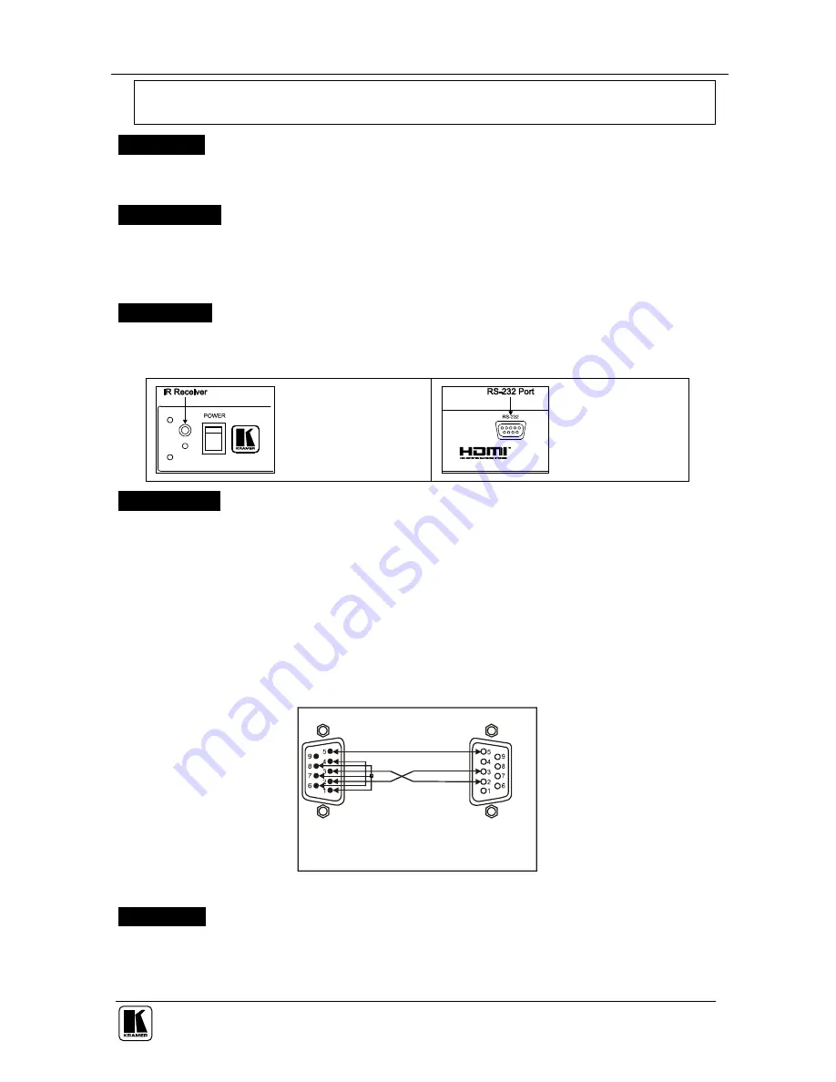
Table A1 describes the additional IR Receiver and RS-232 connector: 

Table A1: IR Receiver and the RS-232 Connector Features 


IR Receiver (front panel) 

The red LED lights when 

receiving signals from the 

Infra-red remote control 

transmitter 


RS-232 DB 9F Port 

(rear panel) 

Connects to the PC or 

the RS-232 Remote 

Controller 

Fourth change


- add before section 6 on page 13:


5.3  Controlling via RS-232 (for example, using a PC) 

To connect a PC to the 

VM-28HDMI

 / 

VM-216HDMI

, using the Null-modem adapter 

provided 

with

 the machine (recommended): 

Connect the RS-232 DB9 rear panel port on the 

VM-28HDMI

 / 

VM-216HDMI


unit to the Null-modem adapter and connect the Null-modem adapter with a 9-wire flat 

cable to the RS-232 DB9 port on your PC 

To connect a PC to the 

VM-28HDMI

 / 

VM-216HDMI

without

 using a Null-modem adapter: 

Connect the RS-232 DB9 port on your PC to the RS-232 DB9 rear panel port on 

the 

VM-28HDMI

 / 

VM-216HDMI

 unit, as Figure A1 illustrates 

Female DB9 (From PC)
PIN 4 Connected to PIN 6
PINS 8, 7, 1 Connected together

If a Shielded cable is used, connect the shield to PIN 5

PIN 5 Connected to PIN 5 (Ground)

PIN 3 Connected to PIN 2

PIN 2 Connected to PIN 3

Male DB9


Figure A1: Connecting a PC without using a Null-modem Adapter 

Fifth change


- add after section 6 on page 13:


8  Kramer Protocol 2000 

The 

VM-28HDMI

 / 

VM-216HDMI

 is compatible with Kramer’s Protocol 2000 (version 

0.46). You can download it from our Web site at: http://www.kramerelectronics.com 

Summary of Contents for VM-212HDMI

Page 1: ...Kramer Electronics Ltd USER MANUAL Models VM 28HDMI 2 Input 1 8 HDMI Distributor VM 212HDMI 2 Input 1 12 HDMI Distributor VM 216HDMI 2 Input 1 16 HDMI Distributor...

Page 2: ...or 11 5 2 Operating the VM 28HDMI VM 212HDMI VM 216HDMI 12 5 2 1 Using the EDID Button 12 5 2 2 Acquiring Changing the EDID 12 5 2 3 Resetting the Default EDID 12 6 Technical Specifications 13 Figures...

Page 3: ...RS 232 Remote Controller Fourth change add before section 6 on page 13 5 3 Controlling via RS 232 for example using a PC To connect a PC to the VM 28HDMI VM 216HDMI using the Null modem adapter provi...

Page 4: ...package includes the following items VM 28HDMI VM 212HDMI VM 216HDMI Power cord This user manual3 2 Getting Started We recommend that you Unpack the equipment carefully and save the original box and...

Page 5: ...switching power supply 3 1 About HDMI High Definition Multimedia Interface HDMI is an uncompressed all digital8 audio video interface widely supported in the entertainment and home cinema industry It...

Page 6: ...ndard definition formats such as NTSC or PAL 3 2 Defining EDID The Extended Display Identification Data EDID5 is a data structure provided by a display to describe its capabilities to an HDMI source T...

Page 7: ...changing the EDID see section 5 2 2 4 EDID Button 2 Press for more than 3 seconds to set to the EDID mode 5 LOCK Button 3 Press to engage disengage the front panel switches 6 OUTPUT STATUS LEDs LEDs l...

Page 8: ...Your VM 28HDMI VM 212HDMI VM 216HDMI 5 Figure 1 VM 28HDMI 2 Input 1 8 HDMI Distributor...

Page 9: ...KRAMER SIMPLE CREATIVE TECHNOLOGY Your VM 28HDMI VM 212HDMI VM 216HDMI 6 Figure 2 VM 212HDMI 2 Input 1 12 HDMI Distributor...

Page 10: ...Your VM 28HDMI VM 212HDMI VM 216HDMI 7 Figure 3 VM 216HDMI 2 Input 1 16 HDMI Distributor...

Page 11: ...how to Connect the VM 28HDMI VM 212HDMI VM 216HDMI see section 5 1 Operate the VM 28HDMI VM 212HDMI VM 216HDMI see section 5 2 Use the EDID button see section 5 2 1 5 1 Connecting the VM 28HDMI VM 21...

Page 12: ...T 8 connector to acceptor 8 for example a plasma display 2 Connect the two HDMI sources for example a DVD player and a set top box to the INPUT 1 and INPUT 2 connectors respectively using the Kramer H...

Page 13: ...e an LCD TV OUTPUT 12 connector to acceptor 12 for example a plasma display 2 Connect the two HDMI sources for example a DVD player and a set top box to the INPUT 1 and INPUT 2 connectors respectively...

Page 14: ...T 16 connector to acceptor 16 for example a plasma display 2 Connect the two HDMI sources for example a DVD player and a set top box to the INPUT 1 and INPUT 2 connectors respectively using the Kramer...

Page 15: ...upply 2 Connect the new output display device 3 Press the EDID button for more than 3 seconds to set the machine to the EDID Reset mode 4 Press an input button either IN 1 or IN 2 1 once The selected...

Page 16: ...Connectors 12 on HDMI Connectors 16 on HDMI Connectors BANDWIDTH Supports up to 1 65Gbps bandwidth per graphic channel COMPLIANCE WITH HDMI STANDARD Supports HDMI 1 2 and HDCP CONTROLS EDID IN 1 IN 2...

Page 17: ...is required the original dated invoice or a copy must be presented as proof of warranty coverage and should be included in any shipment of the product Please also include in any mailing a contact name...

Page 18: ...or the latest information on our products and a list of Kramer distributors visit our Web site www kramerelectronics com where updates to this user manual may be found We welcome your questions commen...

Reviews: