


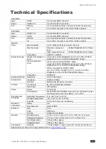
Kramer Electronics Ltd.
TP-873XR / TP-874XR
– Connecting TP-873XR/TP-874XR
8
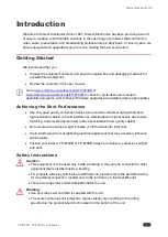
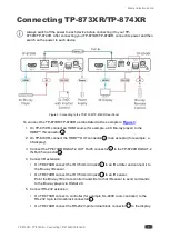
6. Connect the power adapter to the
TP-873XR
power connector
and to the mains
electricity.
You can connect the power adapter to either the transmitter or the receiver since
DGKat 2.0 passes power bidirectionally.
This example shows the power adapter connected to
TP-873XR
but you can
connect the power adapter to the receiver instead.
Connecting to TP-873XR
/
TP-874XR via RS-232
You can connect to the
TP-873XR
/
TP-874XR
via an RS-232 connection
using, for
example, a PC.
The
TP-873XR
/
TP-874XR
features an RS-232 3-pin terminal block connector allowing the
RS-232 to control the
TP-873XR
/
TP-874XR
.
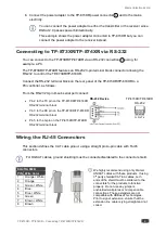
Connect the RS-232 terminal block on the rear panel of the
TP-873XR
/
TP-874XR
to
a
PC/controller, as follows:
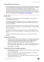
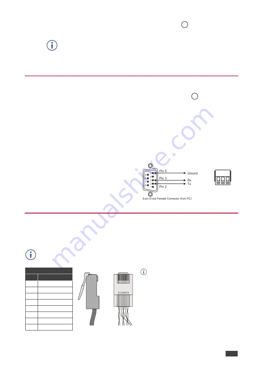
From the RS-232 9-pin D-sub serial port connect:
•
Pin 2 to the TX pin on the
TP-873XR
/
TP-874XR
RS-232 terminal block
•
Pin 3 to the RX pin on the
TP-873XR
/
TP-874XR
RS-232 terminal block
•
Pin 5 to the G pin on the
TP-873XR
/
TP-874XR
RS-232 terminal block
RS-232 Device
TP-873XR
/
TP-874XR
RS-232
G Rx Tx
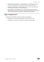
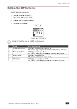
Wiring the RJ-45 Connectors
This section defines the CAT cable pinout, using a straight pin-to-pin cable with RJ-45
connectors.
For DGKAT cables, ground shielding must be connected/soldered to the connector shield.
EIA /TIA 568B
We highly recommend using only Kramer
UNIKAT cables with these products. If using
3
rd
party shielded CAT-6A cables, both
ends of the shield must be soldered to the
connectors for the products to function
properly. Do not use any jumpers,
unshielded wall plates or mid-span cable
connections. These extenders are not
compatible with HDBaseT technologies.
Prior to signal extension, ensure that the
extension line cable is lying straight and not
coiled.
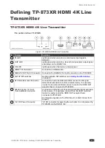
PIN Wire Color
1
Orange / White
2
Orange
3
Green / White
4
Blue
5
Blue / White
6
Green
7
Brown / White
8
Brown
9
13


