


TP-121xl/TP-122xl - Defining the TP-121xl Transmitter and
TP-122xl Receiver
7
7
4.2
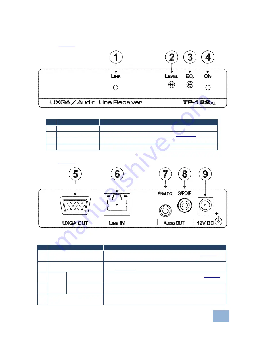
Defining the TP-122xl UXGA/Audio Line Receiver
Figure 3
defines the front panel of the
TP-122xl
.
Figure 3: TP-122xl UXGA/Audio Line Receiver Front Panel
#
Feature
Function
1
LINK
LED
Lights green when the TP link is established
2
LEVEL
Trimmer
Use to adjust the output signal level (see
Section
6.2
)
3
EQ.
Trimmer
Use to adjust the cable compensation equalization level
4
ON
LED
Lights green when the device is powered on
Figure 4
defines the rear panel of the
TP-122xl
.
Figure 4: TP-122xl UXGA/Audio Line Receiver Rear Panel
#
Feature
Function
5
UXGA OUT
15-pin HD
Connector (F)
Connect to a computer graphics video acceptor (see
Section
5
)
6
LINE IN
RJ-45 Connector
Connect to the Line Out RJ-45 connector on the TP-121xl
(See
Section
2.2
)
7
AUDIO
OUT
ANALOG
3.5mm
Mini Jack
Connect to an unbalanced, stereo audio acceptor (see
Section
5
)
8
S/PDIF
RCA
Connector
Connect to a digital audio acceptor
9
12V DC
Power Connector
Connect to one of the su12V DC power adapters. Center
pin positive


