background image

Installing in a Rack 


13 

Installing in a Rack 

This section describes how to install the unit in a rack. 

Before Installing in a rack 


How to Rack Mount 

Before installing in a rack, be sure that the environment is 

within the recommended range: 

Operating temperature range  +5º to +45º C (41º to 113º F) 
Operating humidity range 

10 to 90% RHL, non-condensing 

Storage temperature range 

-20º to +70º C (-4º to 158º F) 

Storage humidity range 

5 to 95% RHL, non-condensing 


 CAUTION

!!


When installing on a 19" rack, avoid hazards by taking 

care that: 

1.  It is located within the recommended environmental 

conditions, as the operating ambient temperature of a 

closed or multi unit rack assembly may exceed the 

room ambient temperature. 

2.   Once rack mounted, enough air will still flow around 

the machine. 

3.   The machine is placed straight in the correct 

horizontal position. 

4.   You do not overload the circuit(s). When connecting 

the machine to the supply circuit, overloading the 

circuits might have a detrimental effect on overcurrent 

protection and supply wiring. Refer to the appropriate 

nameplate ratings for information. For example, for 

fuse replacement, see the value printed on the 

product label. 

5.   The machine is earthed (grounded) in a reliable way 

and is connected only to an electricity socket with 

grounding. Pay particular attention to situations where 

electricity is supplied indirectly (when the power cord 

is not plugged directly into the socket in the wall), for 

example, when using an extension cable or a power 

strip, and that you use only the power cord that is 

supplied with the machine. 


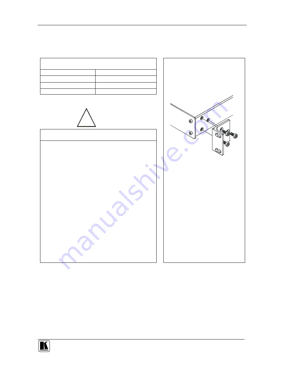
To rack-mount a machine: 

1.  Attach both ear brackets to the 

machine. To do so, remove the 

screws from each side of the 

machine (3 on each side), and 

replace those screws through the 

ear brackets. 


2.  Place the ears of the machine 

against the rack rails, and insert the 

proper screws (not provided) 

through each of the four holes in the 

rack ears. 

Note that: 


In some models, the front panel 

may feature built-in rack ears 

  Detachable rack ears can be 

removed for desktop use 

  Always mount the machine in the 

rack before you attach any cables 

or connect the machine to the 

power  

  If you are using a Kramer rack 

adapter kit (for a machine that is not 

19"), see the Rack Adapters user 

manual for installation instructions 

(you can download it at: 

http://www.kramerelectronics.com) 


Summary of Contents for SD-7588V

Page 1: ...Kramer Electronics Ltd USER MANUAL Models VS 88A 8 x 8 Balanced Audio Matrix Switcher VS 88V 8 x 8 Video Matrix Switcher SD 7588V 8 x 8 SDI Matrix Switcher...

Page 2: ...8V 16 6 3 Connecting an SD 5788V 17 6 4 Connecting the Stereo Audio Input Output 18 6 5 Connecting Several Units and the PC 18 6 6 Connecting a Component Y C RGBS or RGBHV Switcher 19 7 Operation 20 7...

Page 3: ...necting an Unbalanced Stereo Audio Output 18 Figure 10 System Connection Switchers and the PC 19 Figure 11 Component Switcher VS 88V Group Connection 20 Figure 12 Rear Panel DIP switches 22 Tables Tab...

Page 4: ...items Power cord2 Windows based Kramer control software3 This user manual4 2 Getting Started We recommend that you Unpack the equipment carefully and save the original box and packaging materials for...

Page 5: ...KRAMER SIMPLE CREATIVE TECHNOLOGY Getting Started 2 2 1 Quick Start This quick start chart summarizes the basic setup and operation steps...

Page 6: ...on cables2 to avoid interference deterioration in signal quality due to poor matching and elevated noise levels often associated with low quality cables Avoid interference from neighboring electrical...

Page 7: ...g that it remains transparent in almost any audio application Is controllable via the front panel buttons as well as the built in RS 232 and RS 485 interfaces Includes 15 preset memory locations for q...

Page 8: ...Your Matrix Switchers 5 Figure 1 VS 88A 8x8 Balanced Audio Matrix Switcher...

Page 9: ...toggles the mode between the CONFIRM mode 4 and the AT ONCE mode user confirmation per action is unnecessary 9 OUTPUT labels Identifies a connection between the output and the input shown below it IN...

Page 10: ...well as the built in RS 232 and RS 485 interfaces Includes 15 preset memory locations for quickly and easily accessing the most frequently used configurations Functions as a standalone unit as well a...

Page 11: ...KRAMER SIMPLE CREATIVE TECHNOLOGY Your Matrix Switchers 8 Figure 2 VS 88V 8x8 Video Matrix Switcher...

Page 12: ...UT labels Identifies a connection between the output and the input shown below it 11 INPUT Status Display Displays the selected input switched to the output marked above each input 12 Input Status LED...

Page 13: ...and 8 bit video automatically recognizing the word length Accepts analog video as the external source for its vertical interval trigger Is controllable via the front panel buttons as well as the buil...

Page 14: ...Your Matrix Switchers 11 Figure 3 SD 7588V 8x8 SDI Matrix Switcher...

Page 15: ...bels Identifies a connection between the output and the input shown below it 11 INPUT Status Display Displays the selected input switched to the output marked above each input 12 INPUT STATUS LEDs Ill...

Page 16: ...e ratings for information For example for fuse replacement see the value printed on the product label 5 The machine is earthed grounded in a reliable way and is connected only to an electricity socket...

Page 17: ...tchers This section describes how to connect A VS 88A standalone unit see section 6 1 A VS 88V standalone unit see section 6 2 An SD 7588V standalone unit see section 6 3 A balanced or unbalanced ster...

Page 18: ...ced stereo audio recorders to OUTPUT terminal blocks 1 to 8 3 If you are using a PC to control the device connect the serial port of the controlling device to the RS 232 IN 9 pin D sub connector 4 Con...

Page 19: ...to 81 3 Connect up to 2 video acceptors for example composite video displays not shown to the looping SYNC BNC connectors 4 If you are using a PC to control the device connect the serial port of the c...

Page 20: ...ptors for example SDI displays not shown to the looping SYNC BNC connectors or set the 75 termination switch 4 If you are using a PC to control the device connect the serial port of the controlling de...

Page 21: ...the audio and or video input and output cables 3 Connect the video reference input for video for VS 88V and or SD 7588V 4 Set the DIP switches for the different MACHINE Set DIP switch 5 OFF and DIP s...

Page 22: ...nt switcher do the following with every switcher in the group 1 Set the same MACHINE for each switcher for example MACHINE 2 2 Set DIP switch 5 OFF 3 Set DIP switch 6 OFF except on the Master set DIP...

Page 23: ...s section describes the modes setup and the operation of the devices using the front panel controls For instructions on using the Windows based Kramer control software refer to the separate user manua...

Page 24: ...continues to illuminate Any executed action affects all units in the system 7 1 2 Confirmation Modes By default the unit starts in the AT ONCE mode that is if an OUT IN combination is pressed it is im...

Page 25: ...switch Function 1 4 Set the MACHINE NUMBER refer to Table 5 5 Disables use of the IN SYSTEM button OFF enables the IN SYSTEM button ON disables the IN SYSTEM button 6 Enables a reply from the unit af...

Page 26: ...n 30 seconds necessitates restarting that action while the LED display shows the previous state The unit has no control priority Any operation whether from the front panel or from a PC overrides the p...

Page 27: ...itchers Unlocking releases5 the protection mechanism From the PC you can lock and unlock the following A specific switcher All switchers Table 6 Push Button Sequence Summary Lock Unlock Specific Switc...

Page 28: ...FACTOR 0 05 DISPLAY Current switcher status on eight 7 segment bright LEDs CONTROLS 22 front panel touch switches RS 232 and RS 485 control interface SWITCHING During vertical interval from Analog syn...

Page 29: ...26...

Page 30: ...st information on our products and a list of Kramer distributors visit our Web site www kramerelectronics com where updates to this user manual may be found We welcome your questions comments and feed...

Reviews: