background image

Using the RC-53D K-NET Auxiliary Control Panel 


Using the RC-53D K-NET Auxiliary Control Panel 

The installation process is not detailed in this user manual. This user manual is 
applicable once the unit is installed and configured

1


Setting up the labels on the buttons, according to your specific requirements 

, and includes: 


Configuration of the Master room controller via the 

K-Config

 Windows

®

-based 

configuration software  

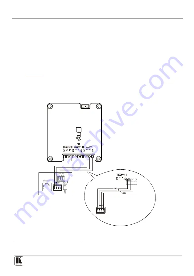
Since the auxiliary panel is used as a remote controller for Master Room 
Controllers via the proprietary communication channel K-NET (as illustrated in 

Figure 3

)


It requires only a K-NET connection to the Master Room controller 


A power supply unit is 

not

 required

2


The auxiliary panel can be programmed only via the Master Room controller 
(for example, the Kramer 

SV-551


SummitView™ Processor/Switcher


Black  = GND

PINOUT

Red    = +12V

Green = A

White  = B


Figure 3: RC-53D connected to the SV-551 SummitView™ Processor / Switcher 


1 By authorized Kramer technical personnel or by an external system integrator 

2 Power supplies are sold separately  Consult your Kramer dealer for details 

Summary of Contents for K-NET RC-53D

Page 1: ...Kramer Electronics Ltd USER MANUAL Model RC 53D K NET Auxiliary Control Panel...

Page 2: ...iary Control Panel Front Panel 3 Figure 2 RC 53D K NET Auxiliary Control Panel Rear Panel 4 Figure 3 RC 53D connected to the SV 551 SummitView Processor Switcher 5 Figure 4 Sample Button Label Sheet 6...

Page 3: ...one of the Kramer SL series controllers The RC 53D Screwdriver This user manual3 2 Getting Started This user manual is written for the end user Refer to the separate K Config Configuration Guide avail...

Page 4: ...not require a separate power supply Includes two K NET ports and an RS 232 serial port for firmware upgrade Features two programmable LCD displays one for each button group To achieve the best perform...

Page 5: ...ature Function 1 SOURCE Buttons Group of four programmable backlit buttons 1 2 Faceplate Screws Four screws connecting the faceplate to the Rear Box 3 DISPLAY and SOURCE Labels Programmable 8 characte...

Page 6: ...unding Screw Connect to grounding wire 3 RS 232 Terminal Block Connect to the RS 232 connector on a PC for firmware upgrade 1 4 K NET Terminal Block Connect the GND to the Ground connection2 5 connect...

Page 7: ...anel is used as a remote controller for Master Room Controllers via the proprietary communication channel K NET as illustrated in Figure 3 It requires only a K NET connection to the Master Room contro...

Page 8: ...els from the supplied button label sheet 2 Hold the button cap so that it is oriented as shown in Figure 5 with the wings on the left and right sides and insert the label inside the cap 3 Repeat for a...

Page 9: ...n 1 minute delay for he projector to heat up The projector selects the DVD input OFF Power down the projector Stop the DVD player Power down the DVD player Stop the VCR Power down the VCR Roll up he p...

Page 10: ...on terminal block connectors 1 RS 232 on terminal block connector 1USB connector POWER SOURCE 12V DC 140mA over K NET FUSE 500mA FSMD 1812 DIMENSIONS For the USA 11 4cm x 2 6cm x 11 4cm 4 49 x 1 02 x...

Page 11: ...eractsofnature ii Product modification orfailureto followinstructions supplied with theproduct iii Repairorattemptedrepairby anyonenot authorized byKramer iv Anyshipment oftheproduct claims must bepre...

Page 12: ...or the latest information on our products and a list of Kramer distributors visit our Web site www kramerelectronics com where updates to this user manual may be found We welcome your questions commen...

Reviews: