background image

Operating the RC-53D K-NET Auxiliary Control Panel 


Operating the RC-53D K-NET Auxiliary Control Panel 

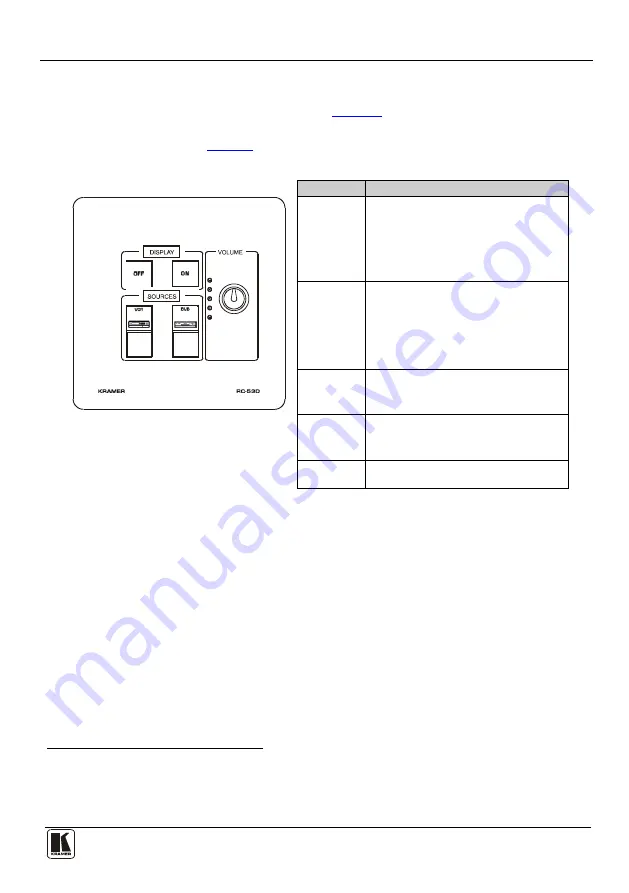
In the following example

1

Figure 6

 (illustrated in 

), the auxiliary control panel is 

labeled with specific functions and each button is programmed

2

 to perform several 

tasks

3

Table 3

 as defined in 

. 

Table 3: The Commands Configuration 


The Label 

The Macro Sequence 


Figure 6: RC-53D Labels Setup 

ON 

  Power up the projector 

  Power up the DVD player 

  Roll down the projector screen 

  1 minute delay (for  he projector to heat 

up) 

  The projector selects the DVD input 

OFF 

  Power down the projector 

  Stop the DVD player 

  Power down the DVD player 

  Stop the VCR  

  Power down the VCR 

  Roll up  he projector screen 

DVD 

  Stop the video player 

  The projector selects the DVD input 

  Play the DVD 

VCR 

  Stop the DVD 

  The projector selects the VCR input 

  Play the VCR 

VOLUME 

  Use the VOLUME knob to adjust  he 

audio level 


1 This is only one example among numerous possibilities, each button can be programmed as required  In this example, two buttons are 

not assigned 

2 By the technical installer 

3 A macro sequence, including several commands per button, carried out one after the other 

Summary of Contents for K-NET RC-53D

Page 1: ...Kramer Electronics Ltd USER MANUAL Model RC 53D K NET Auxiliary Control Panel...

Page 2: ...iary Control Panel Front Panel 3 Figure 2 RC 53D K NET Auxiliary Control Panel Rear Panel 4 Figure 3 RC 53D connected to the SV 551 SummitView Processor Switcher 5 Figure 4 Sample Button Label Sheet 6...

Page 3: ...one of the Kramer SL series controllers The RC 53D Screwdriver This user manual3 2 Getting Started This user manual is written for the end user Refer to the separate K Config Configuration Guide avail...

Page 4: ...not require a separate power supply Includes two K NET ports and an RS 232 serial port for firmware upgrade Features two programmable LCD displays one for each button group To achieve the best perform...

Page 5: ...ature Function 1 SOURCE Buttons Group of four programmable backlit buttons 1 2 Faceplate Screws Four screws connecting the faceplate to the Rear Box 3 DISPLAY and SOURCE Labels Programmable 8 characte...

Page 6: ...unding Screw Connect to grounding wire 3 RS 232 Terminal Block Connect to the RS 232 connector on a PC for firmware upgrade 1 4 K NET Terminal Block Connect the GND to the Ground connection2 5 connect...

Page 7: ...anel is used as a remote controller for Master Room Controllers via the proprietary communication channel K NET as illustrated in Figure 3 It requires only a K NET connection to the Master Room contro...

Page 8: ...els from the supplied button label sheet 2 Hold the button cap so that it is oriented as shown in Figure 5 with the wings on the left and right sides and insert the label inside the cap 3 Repeat for a...

Page 9: ...n 1 minute delay for he projector to heat up The projector selects the DVD input OFF Power down the projector Stop the DVD player Power down the DVD player Stop the VCR Power down the VCR Roll up he p...

Page 10: ...on terminal block connectors 1 RS 232 on terminal block connector 1USB connector POWER SOURCE 12V DC 140mA over K NET FUSE 500mA FSMD 1812 DIMENSIONS For the USA 11 4cm x 2 6cm x 11 4cm 4 49 x 1 02 x...

Page 11: ...eractsofnature ii Product modification orfailureto followinstructions supplied with theproduct iii Repairorattemptedrepairby anyonenot authorized byKramer iv Anyshipment oftheproduct claims must bepre...

Page 12: ...or the latest information on our products and a list of Kramer distributors visit our Web site www kramerelectronics com where updates to this user manual may be found We welcome your questions commen...

Reviews: