


Kramer Electronics Ltd.
16
9.5
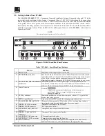
Audio Level Control (FC-4208 only)
A balanced audio signal is made of two antiphase signals, traveling on two wires (sometimes with a third - a
ground reference / shield wire). A balanced signal achieves better signal-to-noise ratio, and is more immune to
noise and interference. On the receiving end there is a differential amplifier, which amplifies only the difference
between the antiphase signals, thus canceling noise which is picked up along the way and which is common
mode. The balanced system is usually used either when very low signals are to be transmitted over long
distances (such as those generated from high quality microphones) or at broadcast audio studios, for highest
quality signal recreation. To control the balanced/unbalanced signal, gently adjust the Level control knobs until
a satisfactory audio level is achieved.
10
TYPICAL APPLICATIONS
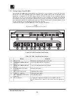
10.1
Interfacing Between Two Video Formats
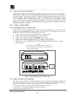
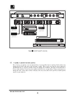
The FC-10D can be used for simultaneous bi-directional conversion from composite video to YC and from YC
to composite for studio applications as shown in Figure
9
. In such a setup, YC signals can be monitored on a
composite video monitor! Perform the following steps (as necessary):
1.
Connect a composite video source to the CV IN connector of the FC-10D.
2.
Connect an YC acceptor to the YC OUT connector of the FC-10D.
3.
Connect an YC video source to the YC IN connector of the FC-10D.
4.
Connect a composite video acceptor to the YC OUT connector of the FC-10D.
5.
Connect the FC-10D to an appropriate 12VDC power supply, with proper polarity.
6.
Operate sources, acceptors and the FC-10D. Press one of the control switches to select PAL or NTSC
mode of operation.
NOTE
The machine cannot convert composite PAL to Y/C in
NTSC. Encoding and decoding is performed only
within the same standard.
Figure
9
: Interfacing Between Two Video Formats
10.2
Using PC Graphics in YC Production
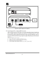
Some scan converters, which convert VGA/XGA graphics to video, generate only a composite video signal. The
FC-10 converts composite video signal to s-Video (YC), thus enabling usage of computer generated graphics in
professional YC productions, as shown in Figure
10
. Perform the following steps (as necessary):
1. Connect a composite video source to the CV IN BNC connector of the FC-10
2. Connect an YC acceptor to the YC OUT 4P connector of the FC-10.
3. Operate source, acceptor and the FC-10.


