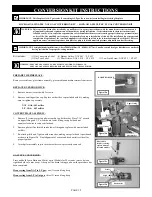
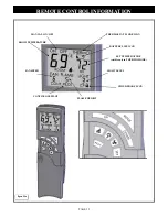
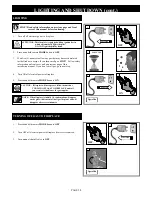
background image

PAGE 26 

FLAME MODE: 

This remote will operate the flame, allowing for (6) different flame height 
levels. When 

MAIN FLAME

 button is pressed,  FLAME level setting will 

flash on the LCD screen. Press 

UP 

or 

DOWN 

buttons to select desired flame 

level. If no adjustment is made within 7 seconds, the control will exit function 
setting mode and LCD display will return to normal view.  

NOTE:  The fireplace will initially light at the highest level. After 5  
               seconds the flame will adjust to last chosen level before  
               fireplace was turned OFF. 


            This applies to MANUAL and THERMO modes. 

Figure 26a 

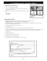
REMOTE CONTROL INFORMATION cont. 

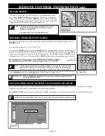
THERMO (THERMOSTAT) MODE: 

This remote feature allows you to thermostatically control the fireplace when hand held remote is set to 

THERMO

 mode.  

 
Set Temperature Range: 45

˚

F (7

˚

C) to 90

˚

F (32

˚

C). 

 
Set remote to 

THERMO 

mode by pressing 

MODE 

button. The smaller 

SET 

window


of numbers appears 

on the LCD screen. The first SET number will read 45

˚

F. Press 

UP

 button to desired set room temperature. 

Within 5 seconds fireplace will operate to that Set Temperature. The 

FLAME,  ON

 and 

THERMO 

icons


will appear on the LCD screen. By pressing 

UP 

or 

DOWN 

buttons a new set temperature may be attained. 


SET Temperature will only appear when THERMOSTAT MODE is activated,  
but is implemented in all MODES with the exception of MANUAL MODE. 


NOTE:  The flame height can adjust up to (6) different height levels according to amount of heat  
               required. This range however is dictated by the Flame Level setting (see previous page).    
               When desired temperature is met, the fireplace will shut off until more heat is required. 

To exit 

THERMO 

mode press the 

MODE 

button. This also shuts fireplace OFF. 

IMPORTANT:  When in THERMO mode the fireplace will not turn on until room temperature falls  


below SET TEMPERATURE. 

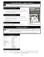
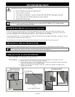
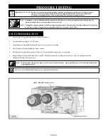
SYSTEM OPERATION WITHOUT HAND HELD REMOTE: 

This system is designed to operate with the hand held remote or a thermostat, but in the unlikely event that it is required to be operated  
without the hand held remote or a thermostat, follow this simple procedure. 
 
Slide 

REMOTE /OFF 

switch on main control module to 

OFF

. The fireplace can now be lit and shut off by use of the ON/OFF rocker 

switch.  

REMOTE / OFF 

NOTE: When operating fireplace in this capacity, the only function available is burner operation on HI.  

Figure 26b 

Figure 26c 

Summary of Contents for MPS-34 Minneapolis XL

Page 1: ...Vehicles and Mobile Housing CSA Z240 4 Do not store or use gasoline or other flammable vapors and liquids in the vicinity of this or any other appliance IF YOU SMELL GAS Do not light any appliance Do...

Page 2: ...on and reliability but customer safety as well We offer our continual support and guidance to help you achieve the maximum benefit and enjoyment from your Kozy Heat gas fireplace Jim Hussong Dudley Hu...

Page 3: ...Conversion Kit Instructions 12 13 GLASS FRAME ASSEMBLY SCREEN FRONT Glass Frame Assembly Screen Front Removal Installation 14 INSTALLATION Approved Venting 14 Combustion Air Venting Options 14 Air Du...

Page 4: ...keep toddlers young children and other at risk individuals out of the room and away from hot surfaces Clothing or other flammable material should not be place on or near the appliance Adequate access...

Page 5: ...Black firebox liner Glass Media Kit IPI control system with remote control Engineer designed burner system Automatic fan kit 1 75 CFM Light Kit Co linear vent system 3 combustion air 3 exhaust Innovat...

Page 6: ...8 feet above grade directly in line with the exhaust vent terminal for the horizontally vented gas fueled heating appliance or equipment The sign shall read in print no less the one half inch 1 2 in...

Page 7: ...t Center FIREPLACE DIMENSIONS INCHES 23 5 8 34 28 3 16 16 3 8 24 1 2 7 1 4 1 3 8 10 1 4 6 1 8 MILLIMETERS 600 864 716 416 622 184 35 260 156 1 Fireplace insert 2 Air chute 3 Module panel assembly 4 Va...

Page 8: ...SPECIFICATIONS PAGE 7 MINIMUM CLEARANCES TO COMBUSTIBLES Figure 7a...

Page 9: ...Glass Media Kit 2 JXL 057T Glass Frame Assembly OCK A53L I MXL PSE LP Conversion Kit 816 CL1 Co Linear Air Duct 700 208 Remote Control 700 GLT Glass Latch Tool Vent System Part 816 CL For use with min...

Page 10: ...nside diameter Existing Chimney Height Minimum 10ft 3 05m Maximum 35ft 10 67m 1 Remove and discard existing chimney cap 2 Position one person at fireplace and another person at top of chimney Measure...

Page 11: ...s screen rails screen mesh and log grates may be removed from existing fireplace before installing this gas fireplace insert Any smoke shelves shields and baffles may be removed if attached by mechani...

Page 12: ...ith the requirements of the ANSI Z223 1 installation code NOTE A listed and Commonwealth of Massachusetts approved 12 13mm manual shut off valve and flexible gas connector included are connected to th...

Page 13: ...so now before installing into existing fireplace REPLACE BURNER ORIFICE 1 Remove burner secured with 2 screws 2 Remove existing orifice cap Replace with orifice cap included with kit making sure to ti...

Page 14: ...pressure Visually check pilot flame Flame should envelope top of flame sensor and extend onto burner far enough for prop er ignition To Adjust pilot Turn pilot adjustment screw clockwise to decrease...

Page 15: ...ith slots on insert set into position To remove Lift frame up and out of slots PAGE 14 Figure 14a INSTALLATION COMBUSTION AIR VENTING OPTIONS OPTION 1 FULL CONNECTION Combustion air intake pipe is run...

Page 16: ...sealant around inner edge at end of exhaust pipe without collar red marking and slide onto corresponding collar on termination cap collar with label Secure with 3 self tapping screws provided Apply ad...

Page 17: ...sen vent system OPTIONAL 816 CL kits Secure termination cap to existing chimney with 2 self tapping screws and anchor straps provided through pilot holes located at sides of termination cap 3 From ins...

Page 18: ...llar on air duct Slide combustion intake pipe over collar Secure with 3 self tapping screws provided To ensure an air tight seal apply additional sealant around joint 4 Slide insert into fireplace ope...

Page 19: ...ION Disconnect all electrical power from fireplace before performing this task NOTE To avoid damage and prolong the life of halogen bulbs never touch with bare hands Always use a soft cloth when handl...

Page 20: ...19a IMPORTANT THIS SYSTEM REQUIRES ELECTRICITY 110 V AND OR BATTERIES TO OPERATE USING BATTERY BACK UP WILL OPERATE BURNER ONLY FAN COMPONENTS WILL NOT FUNCTION ON BATTERY BACK UP POWER Light kit not...

Page 21: ...OR LOW LIMIT SCREW STEP MOTOR WIRE HARNESS MAIN VALVE INTERNAL SOLENOID CONNECTION PILOT INTERNAL SOLENOID CONNECTION PILOT ADJUSTMENT SCREW INLET PRESSURE SCREW OUTLET MANIFOLD PRESSURE SCREW IPI GAS...

Page 22: ...N OFF SWITCH LEARN BUTTON MAIN CONTROL MODULE VALVE STEP MOTOR TERMINAL COMMUNICATION LINK TO EXTENSION MODULE AC ADAPTOR CONNECTION EXTENSION MODULE COMMUNICATION LINK TO CONTROL MODULE POWER TO LIGH...

Page 23: ...CONTROL INFORMATION CHILD PROOF ICON LIGHT LEVEL FLAME HEIGHT FAN SPEED BATTERY LIFE ICON THERMOSTAT MODE ICON SET TEMPERATURE visible only in THERMO MODE MANUAL ON OFF ROOM TEMPERATURE CONTINUOUS PI...

Page 24: ...d may cause an explosion Disconnect 110V before servicing The IPI gas control system has the option of a continuous standing pilot feature This allows you to change from a spark to pilot system to a s...

Page 25: ...n on right side access panel A Velcro strip has been attached to help secure in place The Hand Held Remote operates on 2 1 5V AAA batteries We recommend always using ALKALINE batteries to extend batte...

Page 26: ...ain will turn fireplace OFF NOTE The MODE button operates in a series that will cycle from ON to THERMO to OFF FAN MODE This remote will operate the fan allowing for 6 different speed levels When the...

Page 27: ...ature The FLAME ON and THERMO icons will appear on the LCD screen By pressing UP or DOWN buttons a new set temperature may be attained SET Temperature will only appear when THERMOSTAT MODE is activate...

Page 28: ...P CHILDREN CLOTHING AND FURNITURE AWAY This appliance needs fresh air for safe operation and must be installed so there are provisions for adequate combustion and ventilation air WHAT TO DO IF YOU SME...

Page 29: ...not operate follow instructions TURNING OFF GAS TO FIREPLACE and call your service technician or the gas supplier ATTENTION This fireplace is equipped with an ignition device which automatically light...

Page 30: ...re Follow instructions below for proper testing procedures INLET PRESSURE TEST PRESSURE TESTING NOTE If inlet pressure reading is too high or too low contact the gas company Only a qualified gas servi...

Page 31: ...ot flame is actually present when valve is turned OFF if yes replace valve Replace pilot assembly Replace module SENSOR SAFETY Protection for Flame Sensor Error Code Four beeps every two seconds Descr...

Page 32: ...YOUR INSTALLATION NATURAL GAS LP PROPANE GAS 1 16 2 mm OPEN 5 8 16mm OPEN BURNER TUBE VENTURI ADJUSTMENT GUIDELINES VENTURI POSITION FLAME COLOR VENTURI ADJUSTMENT Closed too far Dark orange flame wit...

Page 33: ...d agency is required IF VENT AIR INTAKE SYSTEM IS DISASSEMBLED FOR ANY REASON RE INSTALL PER INSTRUCTIONS PROVIDED WITH INITIAL INSTALLATION The flow of combustion and ventilation air must not be obst...

Page 34: ...ing for a beep from receiver when ON is pressed on hand held remote If you do not hear a beep ensure main control module has learned the hand held remote See above Ensure black lead from pilot assembl...

Page 35: ...may take up to 3 hours for the temperature inside a packaged transmitter and several minutes for an unpackaged transmitter to equalize with room temperature FIREPLACE WILL NOT RESPOND IN THERMO MODE...

Page 36: ...Natural Gas Orifice 41 700 404 MXL 1 Minneapolis XL IPI Valve LP 700 253 LP Gas Orifice 53 700 200 Pilot Assembly Natural Gas OCK A41N I MXL PSE Natural Gas Conversion Kit 700 200 1 Pilot Assembly LP...

Page 37: ...PAGE 36 LIMITED WARRANTY...

Page 38: ...PAGE 37 LIFETIME WARRANTY...

Reviews: