Kospel EKCO.R2 Assembly And Operating Manual Download Page 4

4

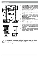
1.  Hang the boiler up in a vertical position 

on  fixing  screws  with  the  inlet  and 

outlet pipes to the bottom, maintaining 

clearances  from  the  walls  and  the 

ceiling according to the figure.

2.  Connect  the  boiler  to  the  central 

heating system equipped with cut-off 

valves.

3.  Fill  the  central  heating  system  with 


a treated water or ERGOLID fluid that 

substantially  extends  the  life  of  the 

heating elements.

4.  Vent the central heating system.

5.  Connect  a  boiler  to  the  electrical 

system.

6.  Fix the room thermostat, in accordance 

with manual instruction.

7.  Connect the room thermostat (by using 

two wires 2 x 0,35 mm

2

) to the NA entry 

(„Connection of external appliances on 

page 6”).

8.  Once  you  have  finished  the  above 

procedures,  you  can  start  the  boiler. 

See the „start-up” section.

!

While applying a thermostat make sure there is no voltage on its exit!
Do not connect any voltage into NA entry! This can result in permanent 

controller damage.

e

e

4 0   5 0   6 0   7 0   8 0

4 5   5 5   6 5   7 5   8 5 

O

  C

Return Inlet  

     Flow Outlet

Return Inlet  

     Flow Outlet

Installation

Summary of Contents for EKCO.R2

Page 1: ...Assembly and operating manual Electric Central Heating Flow Boiler EKCO R2...

Page 2: ...e and knowledge about the product provided that they have been given supervision or instruction concerning safe usage of the appliance and that they are aware of potential dangers that might result fr...

Page 3: ...rough the boiler and reduces a noises in installation during the thermostatic valves closing The valve must be installed in by pass conduit before the boiler according to manufacturer s instruction 7...

Page 4: ...tral heating system 5 Connect a boiler to the electrical system 6 Fix the room thermostat in accordance with manual instruction 7 Connect the room thermostat by using two wires 2 x 0 35 mm2 to the NAe...

Page 5: ...st be installed in horizontal position accordingly to flow direction see arrow on the filter body with the magnetic insert chamber to the bottom Connection to the three phase electrical system PNL poi...

Page 6: ...oper flow through the boiler is reached 4 indicator is on with a constant light The pump should self vent after a short period of running if necessary assist the venting process in the following way c...

Page 7: ...When the indicator 4 flickers it means that the boiler haven t achieved required flow level and the heating is off To set the temperature press 7 or 8 button The display 6 shows the current setting of...

Page 8: ...tion Indicators on the front panel do not light up no power supply for the boiler Check parameters of the power network and fuses Contact your local authorised service the indicator 4 red is flickerin...

Page 9: ...e MPa 0 3 Min pressure MPa 0 05 Outflowing water temp C 35 85 Max water temp C 100 Overall dimensions height x width x depth mm 660 x 380 x 175 Weight kg 18 Water connection G 3 4 Safety class IP 22 T...

Page 10: ...5x1 5 Max connecting wires section mm2 3x16 5x16 The maximum allowed network impedance 0 27 0 17 0 15 0 27 Rated power kW 12 15 18 21 24 Rated voltage 380V 3N Rated current A 3x18 3 3x22 8 3x27 4 3x3...

Page 11: ...uipment for recycling Appropriate utilisation of used product prevents potential negative environmental influences that may occur as a result of inappropriate handling of waste In order to get more de...

Page 12: ...KOSPEL S A 75 136 Koszalin ul Olchowa 1 tel 48 94 31 70 565 serwis kospel pl www kospel pl...

Reviews: