


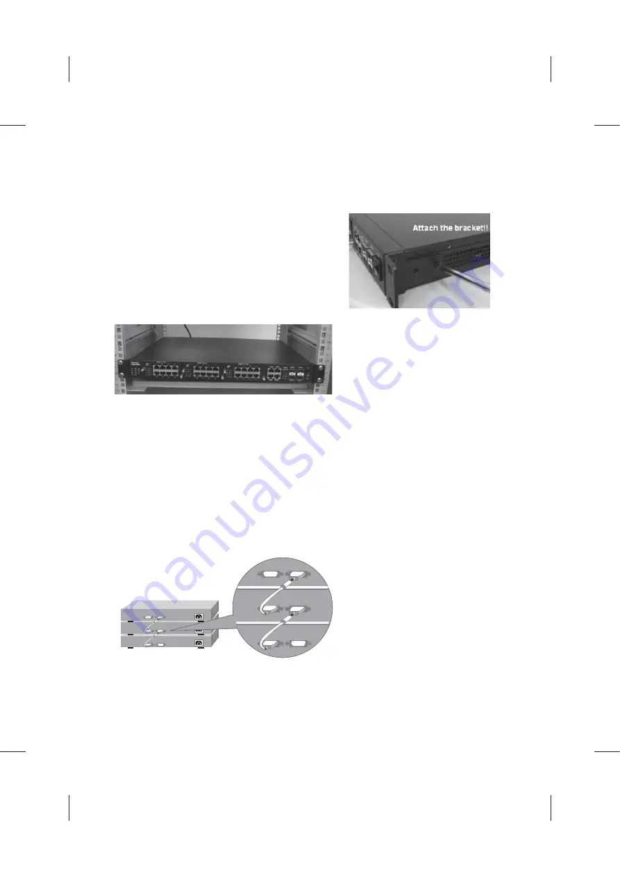
3. Mount the Switch to 19’’ rack
3.1 Attach the brackets to the device by using the screws provided in the Rack Mount kit.
3.2 Mount the device in the 19’ rack by using four rack-mounting screws provided by the
rack manufacturer.
3.3 When installing multiple switches, mount
them in the rack one below the other.
4. Stacking the Switches: A total of 8 switches can be put into a single stack. Stacked
JetNet 6524G Switches can be assigned a single IP address using the switch's
management software. The stack can then be treated as a single manageable unit with one
IP address.
1. Make sure all switches in the stack are powered off.
2. Connect switches through the HighGig ports in the backplane.
3. Power on the switches.
4. The Link LED in the rear panel indicates the link status of the stacking port.
Note:
Korenix provide the stacking cable for purchasement. When the volume of the
stack is under 4, the JNSC-CX405M-S, 50cm stacking cable is enough. When the volume
is above 4, additional one JNSC=CX401M-S, 100cm stacking cable is required for the
connection from the unit 1 to the last unit.
Note:
Check if the rack environment
WHPSHUDWXUHFRQIRUPVWRWKHVSHFL¿HG
operating temperature range. Do not
place any equipment on top of the
switch and please properly grounded.
Summary of Contents for JetNet 6524G
Page 23: ...HW1HW 3 3 LJK LJ AWG...
Page 26: ......