20
Electrical installation
Operation Manual Expansion Module SO CM-E
1800.202B.0-01 Date: 02/2019
X6
X11
X8
L1
L3
L2
11
19
12
24 V
GND
X5.1
X3
X3
X4
X5.2
DC Link -
DC Link+
GND
+24 V
X7
X8
X9
X10
X3
X4
BR X1
X1
X2
2
5
z
Netz/Line
PE
ZK
BR
X11
BR
15
7
DC Link+/-
GND
+24 V
F3
X3
X4
X6
X11
8
X5.1
X3
X4
X5.2
DC Link -
DC Link+
GND
+24 V
X7
X8
X9
X10
W
U
V
X12
Motor
3~
3
2
2
W
U
V
X14
Motor
3~
3
2
2
W
U
V
X13
Motor
3~
3
2
2
BRK
Motor
PELV
BI
ZK
PELV
PELV
PELV
PELV
PELV
PELV
PELV
L1 L2 L3 PE
L3
L2
L1
L3.1
L2.1
L1.1
1
14
13
6
L1 N
3
25
X5
X5
Motor1
3~
3
2
2
2
TEMP
BRAKE
5
L3
L2
L1
L3.1
L2.1
L1.1
W
U V
Motor2
3~
3
2
W
U V
TEMP
BRAKE
MOTOR
2
MOTOR
1
PELV
BI
ZK
PELV
PELV
PELV
PELV
PELV
VI
PELV
PELV
PELV
PELV
ZK
X6
X6
TP
PELV
PELV
PELV
BI
Netz
X6
X6
PF
EXP
PELV
PELV
BI
VI
X6
X6
DI
PELV
PELV
X7
ES
PELV
PELV
PELV
X2
24 V
X1
DC Link
PELV
ZK
(1) Mains fuse for DC link supply
(11) Supply unit SO CM-P BG3/4
(2) 24 V DC power supply unit (external)
(12) Axis controller SO CM BG3/4
(3) Mains contactor (optional)
(13) Switch cabinet
(5) Mains filter (accessory)
(14) Panel
(6) Mains choke (accessory)
(15) Braking resistor with temp. monitoring (external)
(7) SO CM-E expansion module
(19) Star topology protective earth conductor via PE rail
(8) Axis controller SO CM BG1/2
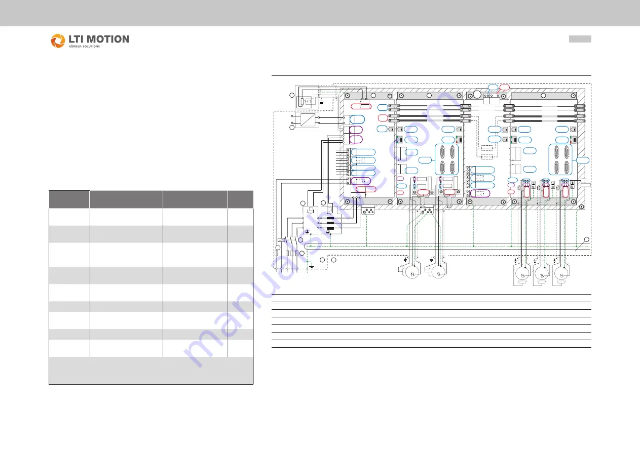
Figure 4.3 Electrical isolation concept with key
4.5 Electrical isolation concept
The control terminals are designed as protective extra low voltage
(PELV) circuits and must only be operated with such PELV voltages,
as per the relevant specification. This aspect provides reliable
protection against electric shock.
The connections DC Link +/-, Motor1 U/V/W, Motor2 U/V/W are at
mains potential (low voltage).
The overview opposite shows the potential references for the
individual connections in detail. This concept also delivers better
operational safety and reliability of the axis controllers.
Connections
SO CM-E (7)
Description
Potential
Abbre-
viation
Busbars
24 V DC
Control section
supply voltage
Protective extra low
voltage circuit
3)
PELV
Busbars DC
Link
DC link
supply voltage
Low voltage
1)
ZK
X1/ DC Link
(terminal)
DC link supply to the 2nd
SO CM-E via terminal and
pre-assembled cable
5)
Low voltage
1)
ZK
X2/ 24 V DC
(terminal)
24 V supply to the
2nd SO CM-E
Protective extra low
voltage circuit
3)
PELV
X3 / X4
Cross-communication
Protective extra low
voltage circuit
3)
PELV
X5 / REL
Relay contact
Reinforced insulation
VI
X6 / State
Dig. outputs (TP, REL)
Protective extra low
voltage circuit
3)
PELV
X7 / ES
"Internal" quick shutdown
PELV
X11 /
Safe - DI
Safe digital inputs
Protective extra low
voltage circuit
3)
PELV
1) Low voltage = AC: U ≤ 1000 V, 2) Single isolation from the low-voltage network and PELV network
3) PELV (Protective Extra Low Voltage)
AC: U ≤ 50 V One connection for the extra low voltage is earthed.
4) Safe isolation from the low-voltage network and PELV network, 5) See .......
Table 4.4 Key to the overview "Electrical isolation concept"


