Kool Sci My Garden Assembly Download Page 18


18

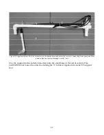
Each Garden comes with 6 solar panel supports, 2 each for the E, S, and W sides.  Almost always 
keep a panel on the E side to catch the morning sun.  The 2

nd

 panel is usually best positioned on 

the S side but that depends on time of year and position of shade on your Garden spot.  Sometimes 
an intermediate orientation is required e.g. SW. Panel wires are extra-long so you can position 
them anywhere around the Garden if it becomes necessary. Insert all 6 supports but when a side is 
not in use rotate the supports in line with the Garden and out of the way.  They rotate easily.  Run 
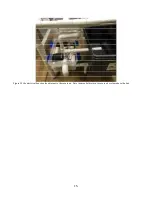
the panel wires through a hole in the appropriate elbow on the electrical box and plug them in to 
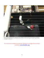
the wire leads connecting to “PV Panels – In” inside the box (see Figure 24).  There is no on/off 
switch for the panels, simply turn them over or cover them with cardboard when you must shut 
them off e.g. for a minute during nutrient solution change out.   
 
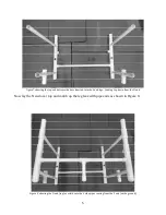
Although the Rule pump is very reliable a breakdown can quickly ruin the garden. It is 
recommended to keep a spare handy.  The filter is a combination filter/ball valve.  Nothing inside 
the Reservoir is glued since small leaks there do no harm.  Pull the ball valve apart frequently to 
check and clean the screen inside.  If the Reservoir is kept closed there is seldom a filter problem 
after the first week of growing.  The ball valve provides some adjustment if/when needed.  In most 
cases on solar outdoors the valve is left wide open. 
 
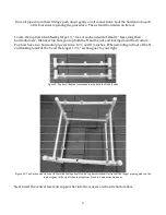
Cut the autoshade reflective cover in half with scissors.  Place half atop the closed Reservoir where 
it effectively reduces solar heating of the nutrient solution (In Florida summers the solution has 
been measured at 110 degrees way too hot for the roots of almost all crops).  Place the other half 
on the Electrical Box to protect the plastic.  Without protection one growing season in the sun can 
destroy the plastic.  A thorough, overlapping cover is essential to preserve the electrical box. 
 

CONGRATULATIONS 

You’ve assembled MyGarden. Add a couple of gallons of water to the Reservoir and start up the 
system to check for leaks and to rinse the system Leaks can occur in transit. Potential leak points 
include the Level Control Valve in the reservoir (tighten the white nut underneath) and the 
Manifold Ports (turn the GroPipes another revolution to tighten the threaded connections.


Even 

tiny leaks can never be tolerated because they lose not only easily replaced water but also 
nutrients!  
 
Read the detailed Operating Instructions carefully for much more information 
 

AUTOFILL 

Check nutrient solution levels on a regular basis.  During germination and early seedling growth 
the level will drop very little.  If necessary, add a small amount of water to return the level to the 
fill line.  If growing seedlings for transplant Autofill won’t be necessary.  If growing a full crop in 
the Garden, however, one month after planting you may be adding water daily.  Once crops are 
producing e.g. large tomato plants you may be adding significant quantities of water twice daily 
(depending on temperatures and sunlight intensity).  Large plants transpire lots of water to keep 
cool especially on hot, sunny days, making automatic watering a must.  
 
There are 7 parts to 

AutoFill

:  

1. No-leak hose bib, the closer to the Garden the better (customer provides)  

Summary of Contents for My Garden

Page 1: ...e receive the hot direct afternoon and evening sun The Garden s functional components reservoir and electrical box are located at the N end and Garden expansion occurs linearly to the S end Use QPlugs only NEVER use soil or loose growing media with the Garden The small bore spaghetti tubing will clog Keep the Electrical box closed and sealed There s lots of water around the Garden that s incompati...

Page 2: ...hed to its support bar Outside and in front of the reservoir is the pump and combination flow valve control filter system small bag of supporting items the return to reservoir drainpipes solar panel supports 2 of 6 shown rubber mallet and GroPlugs behind mallet Inside reservoir is the electrical box bottom Autofill above plant nutrients and battery charger immediately in front Above the reservoir ...

Page 3: ...while the N bottom bar includes a short middle leg that will support the Reservoir Figure 3 Leg bundles S end top N end bottom of picture Open the S end bundle and insert the S end bottom bar into the 2nd from the bottom tees on both legs Note that there are lots of tees making up each leg Do not twist them Put aside the S end Figure 4 This makes the S end once the straight bar is inserted into th...

Page 4: ...e the bottom bar and reservoir support is inserted into 2nd from the bottom tees on each leg Locate the side bottom bars the only components made with crosses Figure 6 side bottom bars As always the feet caps go down Lay the S end flat on the ground Insert the longer of the 2 side bottom bar pipe segments into the lowermost S end leg tees The side top bars are straight pipes Insert them into the t...

Page 5: ... inserted into the S end legs Looking top down from the N end Now lay the N end over top and match up the leg tees with pipe ends as shown in Figure 8 Figure 8 showing the N end top overlaid onto the 4 side pipes coming from the S end on the ground ...

Page 6: ...ing down the structure Top bars have two horizontal pipe sections 12 and 8 inches When standing in front of the N end looking towards the S end the longer 12 section goes to your right Figure 9 Top bars identical components atop both the N and S ends Figure 10 The Garden structure on its feet with the identical N and S top bars attached Notice that the longer pipe segment on the top bars goes to t...

Page 7: ... 2 liter bottles another optional method of production in MyGarden Figure 12 showing plant support bars often replaced with the plugs when crops are small The small holes in the long horizontal pipes not shown in the pipes above are for bottle support straps if the option for a GroBottle option is selected Locate the manifold illustrated upside down in Figure 13 below Make certain the 5 ports are ...

Page 8: ...ring testing add additional tape PLUMBING Figure 13 the drain manifold and return to reservoir section shown here upside down The 5 manifold ports point to the S end to accept the GroPipes and the return to reserve sits below underneath pointing towards the reservoir see Figure 14 Figure 14 view from N end to S end illustrating how one threaded GroPipe supports the manifold in place above the N to...

Page 9: ...5 is a view from the S end looking towards the N end and the manifold held in place using one threaded GroPipe Note return to reservoir section below the top bar Figure 16 The 5 GroPipes installed on the manifold ...

Page 10: ...mp and filter system inside the reservoir vertical section irrigation tube 1 2 rubber tube nutrient solution manifold and five spaghetti distribution tubes one to each GroPipe Everything is preassembled Insert the irrigation support bar s vertical pipes into the middle tees on N and S end s top bars The irrigation manifold goes to the S end The vertical connection system to the reservoir is flexib...

Page 11: ...the reservoir connecting to the pump and filter system inside the reservoir through a small 1 hole Free the spaghetti tubes and stick one down into the small holes at the end of each GroPipe CAUTION Do not loosen the cable ties holding the rubber irrigation tube on its PVC support bar ...

Page 12: ... either once or twice per day and Add On Units AOU which set up easily and double and triple MyGarden production for little additional cost Autofill is not necessary to start out and when the Garden is used to germinate small seedlings for transplanting when growing miniature vegetables or under artificial lights Autofill is almost essential however when growing larger crops especially in hot sunn...

Page 13: ...though water is easily replaced especially with Autofill lost nutrients are not replaced until the next nutrient solution change out Place a paper under the base of the Valve and put 4 gallons of water in the reservoir to check for leaks If you see no drips you re good continue with assembly If the Valve does drip rare turn it over and carefully tighten the large white nut If dripping persists ver...

Page 14: ...e the 2 holes in the reservoir wall the smaller and larger accommodate respectively the vertical section of the irrigation system and the return to Reservoir pipe The level control valve inside Reservoir ships installed in every Reservoir The silver connector below the Reservoir is part of the optional AutoFill Reservoir support board not shown ...

Page 15: ...15 Figure 22 the electrical box situates adjacent to the reservoir Note the manifold return to reservoir system above the box ...

Page 16: ...x Newer Reservoirs lack the wire slit in the upper rim and the wires pass through the same hole as the vertical valve filter irrigation assembly Pump positioning and attachment methods vary The most current assembly and operations instructions and suggestions are always available at www KoolSci org ...

Page 17: ...The electrical box serves to connect the solar panels directly to the pump and to a charge controller that keeps a small battery fully charged We find it satisfactory for the timer to run the pump off the battery for 2 minutes at 10a noon 2p 4p and 6p On sunny days the battery is irrelevant as the panels power the pump On rainy cloudy days however plants still transpire slowly and eventually wilt ...

Page 18: ...d Reservoir where it effectively reduces solar heating of the nutrient solution In Florida summers the solution has been measured at 110 degrees way too hot for the roots of almost all crops Place the other half on the Electrical Box to protect the plastic Without protection one growing season in the sun can destroy the plastic A thorough overlapping cover is essential to preserve the electrical b...

Page 19: ...ay be stopped by wrapping Teflon tape over the bib threads As a last resort replace the bib Install batteries into the timer and program it per instructions With medium leaf area setting the timer to refill the reservoir once daily is adequate Large leaf areas e g several giant tomato plants growing over the Overhead Rack you ll need to re up the reservoir twice daily We suggest on for 2 minutes a...

Page 20: ...valve sit back and watch the Garden take care of itself It s a beautiful thing More Autofill information available in the Operating Instructions Check the website frequently for Assembly and Operating Instruction updates and revisions as well as for fun project based learning ideas control The reservoir support board not shown in this illustration showing the two Autofill components best installed...

Page 21: ...21 ...

Reviews: