CHECK, MAINTENANCE, CLEANING
- during maintenance work, check for possible hazards
- to care for the product, use a damp cloth and a non-abrasive
-
cleaning agent.
TECHNICAL DATA
Material
Tubes, desk: Steel, powder coating, black
Screws, disks: Steel galvanized
Plastic parts: PA, PE, TPE black
Dimensions
Plate: 356 mm wide, 238 (253) mm high
Cantilever: 240-400 mm; 160 mm adjustment range
Height: 278 - 420 mm; 150 mm adjustment range
Weight
2.2 kg
Packaging
L x W x H: 385 x 385 x 75 mm
KÖNIG & MEYER
GmbH & Co. KG
Kiesweg 2, 97877 Wertheim, www.k-m.de
18815-018-55 Rev.16 03-80-343-00 1/19
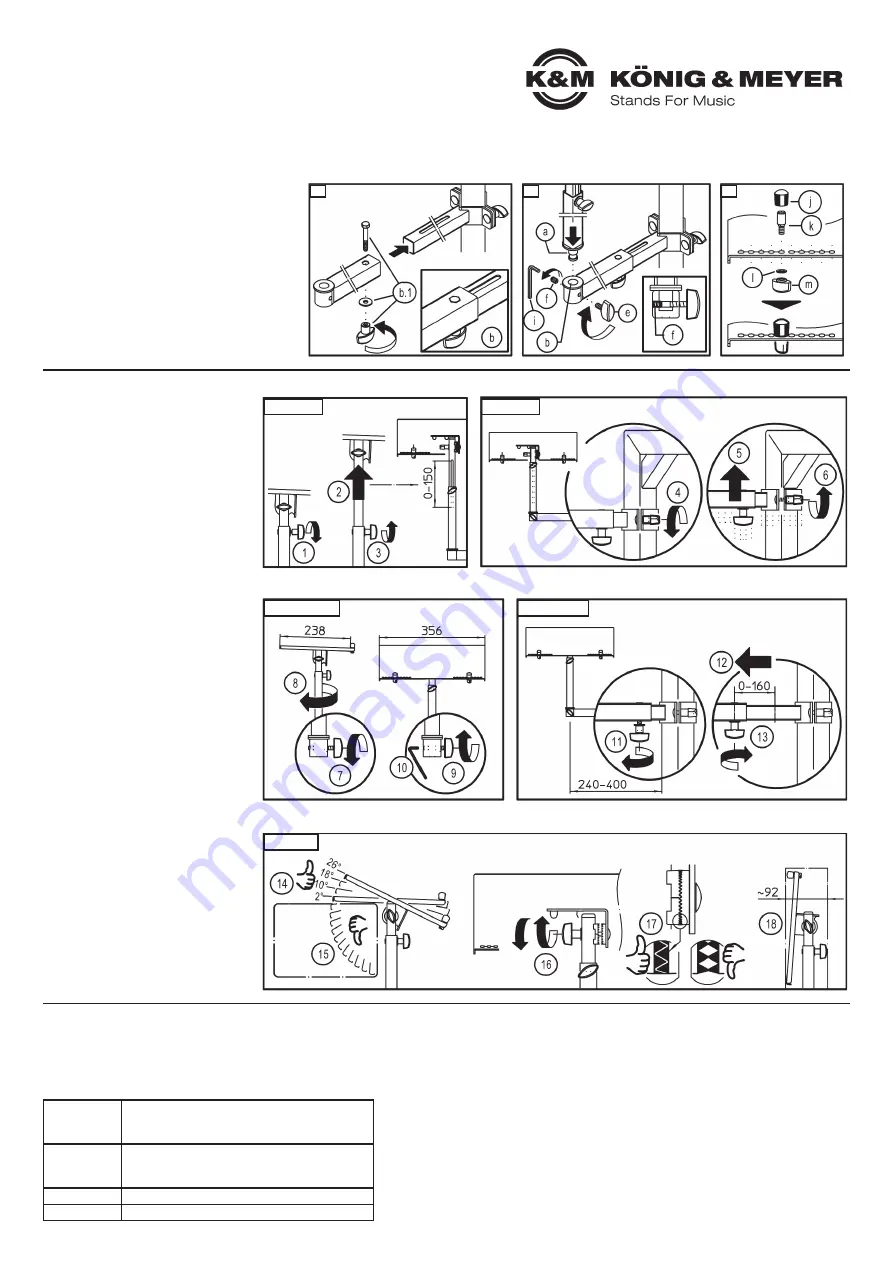
4. MOUNT THE LAPTOP-DESK
Assembly of the individual components
12
Desk and adjustment tube foldable
b
come pre-
12
assembled. By removing the screw connection
b.1
12
both tubes can be separated. (e.g. for maintenance
12
or cleaning purposes).
13
Place the laptop bracket bolts
a
into the adjustment
13
tube
b
and secure this connection by screwing the
13
threaded pin
f
. Use Allen wrench / Hexagon key
13
SW3 for this purpose. This pin is to be screwed into
13
so far that the laptop bracket
a
is secure but still can
13
be moved, i.e. but cannot be pulled out. Then
13
tighten the clamp screw
e
.
14
Place the edge bolts on the desk plate:
14
- Based on the laptop size, place the edge pints on
14
-
the plate (10 on both sides).
14
- Place the bolts
k
through the appropriate drill
14
-
holes and secure using washers
l
and clamp
14
-
nuts
m
.
14
- Place caps
j
on the bolts.
USAGE NOTES / FUNCTION / DIMENSIONS
5. ADJUSTMENTS
Any adjustments to the settings must only be
done without the laptop on the desk.
D HEIGHT - Extension (0-150 mm)
1
1
Loosen the clamping screw
a.1
slightly
1
2
Place the extension tube in the desired
12
position.
1
3
Then re-tighten the clamping screw.
E HEIGHT - Mount (only for 18810 »Omega«)
1
4
Loosen the clamp
g
of the prism bracket
c
.
1
5
Place the bracket and prism bracket
1
6
Re-tighten the clamping screw.
F DIRECTION
1
7
Loosen the clamping screw
e
/
13
slightly
1
8
Place the laptop desk
a
in the desired
18
position.
1
9
Re-tighten the clamp screw.
10
If needed, tighten the threaded pin
f
.
G DISTANCE
11
Loosen the clamping screw
b.1
slightly
12
Place the bracket into the desired position.
13
Re-tighten the clamp screw.
H ANGLE
14
For safety reasons, only the front four
14
angles of the desk may be used. The
14
edge pins must be placed at the lower
14
end of the plate.
14
- The largest downward angle is 26°
14
- Followed by 18°, 10° and 2°.
15
WARNING!
15
The plate may not be angled further
15
backwards, because the laptop may fall
15
off the desk.
16
Loosen the wing nut somewhat until the
16
teeth are no longer engaged, set the desk
16
angle using one of the four permitted
16
angles
14
and re-tighten the wing-nut.
17
NOTICE!
17
The teeth of both resting disks must be
17
properly aligned, the teeth must line up
17
properly.
18
TRANSPORT- / PACKAGING
18
The desk has a small footprint and can be
18
stored in the folded position.
12
13
14
D HEIGHT
F DIRECTION
H ANGLE
G DISTANCE
E HEIGHT
FAULT-FINDING (F) and REPAIR (R)
F: Installation is not stable.
F:
B: Check to see if the parts are in the right position and threads are properly tightened.
F: B:
In particular:
F: B:
- Mounting bracket and adjustment adapter (see
3
)
F: B:
- Telescope tubes (see
D
,
G
)
F: B:
- Desk edge pins (see
14
)
F: B:
- Desk joint brackets (see
16
)
F: B:
- The teeth must be properly aligned (see
17
)
F: Laptop does not stay securely in place
F:
B: Check and ensure that the desk is not tilted to steeply.
F: B:
The following 4 front angles are permitted: 26° - 18° - 10° - 2°
Positions
in
encumbered
condition
NOT
PERMITTED


