


ViZion DR+ 1417CK Wireless Calibration Guide v1.0
Ultra UAI v4.1.0.X
8
Customer Support
1.800.366.5343 –
VZ0148UG201611-1.0
3.3 Performing Panel Defect
Calibration
NOTE
:
This step is optional.
After
performing a Gain Calibration, continue by
performing a Defect Calibration (only
necessary if dead pixels and/or dead pixel
lines are present in acquired images). A
new defect map applies these corrections to
mask out dead pixels when possible.
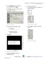
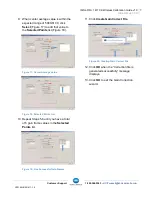
1. In the Correction section, configure the
following setting.
Offset
= NO
2. Click
Create
.
Figure 21: Correction Settings
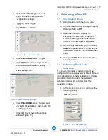
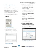
3. Select the
Defect
tab.
The Current
Frame # defaults to “1”. A total of 19
frames must be acquired to complete a
full defect mapping.
Figure 22: Defect Calibration
4. Configure the dose as close to the
requested kV as possible, trying to
adjust mAs to get within
±
100 of the
expected gray value (some deviation of
kV may be required).
The suggested mAs values to use for
each frame are in parenthesis below.
Adjust mAs up or down as needed.
Frame 1: 70kV / expected gray value =
1000 (0.6 mAs)
Frame 2: 40kV / expected gray value =
1000 (5.1 mAs)
Frame 3: 100kV / expected gray value =
4000 (1.2 mAs)
Frames 4-19: 70kV / expected gray
value = 11000 (10.5 mAs
)
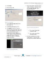
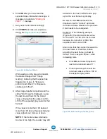
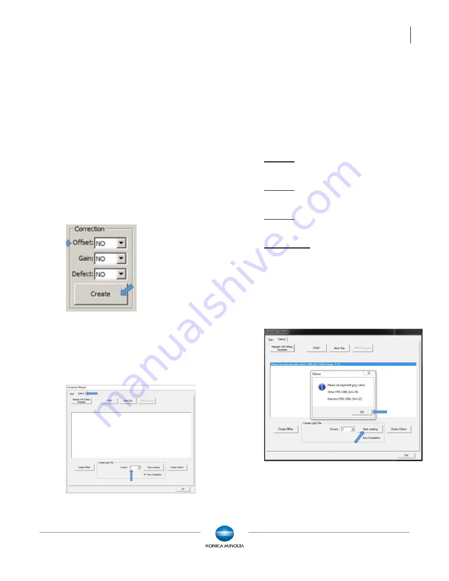
5. Click
Start Creating.
A message
displays providing the amount of kV to
use for that frame #. The message also
provides the expected gray value for
that frame #.
Figure 23: Expected Grey Value Message


