Konica Minolta ViZion DR+ 1417CK Calibration Manual Download Page 3


ViZion DR+ 1417CK Wireless Calibration Guide v1.0 

Ultra UAI v4.1.0.X


Customer Support 

1.800.366.5343 – 

[email protected]


VZ0148UG201611-1.0 


Calibrating ViZion DR+ 

(1417CK)


This guide provides detailed instructions on how to run a full gain and defect calibration for your ViZion 
DR+ 14x17CK wireless panel once the installation process has been tested and verified.  

Panel models can be determined by the first 4-5 digits of the serial number as follows:  

Model 

Panel AKA 

Serial Number Format 

iRay 14x17 Wireless Panel GOS 

G 1417CK Panel 

KV070

XXXXXXXX 

iRay 14x17 Wireless Panel GOS 

G 1417CK Panel 

KV38

XXXXXXXXX


iRay 14x17 Wireless Panel CSI 

C 1417CK Panel 

KV300

XXXXXXXX


1  Preparing for Calibration 

1.1  Recommended Panel 

Configurations 

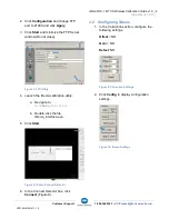
Prior to starting panel calibration it, is 
recommended that basic device configuration is 
setup properly in the ViZion DR+ acquire 
software. 

Refer to the appendix in the technician folder 
for specific configuration details. 

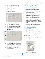
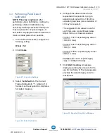
1.2  Powering on the Panel  

Before you power on the panel, allow the panel 
to acclimate to room temperature if the panel is 
brought in from the cold or heat or if room 
environmental controls have been changed. 

1.  Turn panel over and position it so that 

battery connector pins, located in the 
top left of the battery compartment, are 
pointed toward you.  


Figure 1: Panel Positioning for Inserting Battery 

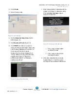
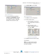
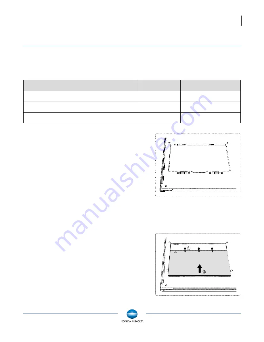
2.  Slide a fully charged battery into the 

battery compartment, aligning the arrow 
on the battery with the connector pins. 


Figure 2: Panel and Battery Alignment 

Summary of Contents for ViZion DR+ 1417CK

Page 1: ...ViZion DR 1417CK Calibration Guide...

Page 2: ...ion DR 1417CK 2 1 Preparing for Calibration 2 1 1 Recommended Panel Configurations 2 1 2 Powering on the Panel 2 1 3 Stopping the Maven Process 3 2 iDemo 3 2 1 Connecting to iDemo 3 2 2 Configuring iD...

Page 3: ...anel KV300XXXXXXXX 1 Preparing for Calibration 1 1 Recommended Panel Configurations Prior to starting panel calibration it is recommended that basic device configuration is setup properly in the ViZio...

Page 4: ...easing Figure 4 Power Button 1 3 Stopping the Maven Process 1 Exit the ViZion DR acquisition software 2 Stop the Maven process if it is running a Verify if Maven is running An iRayMk3 icon is displaye...

Page 5: ...ow Do not close Figure 7 FTP Utility 4 Launch the iDemo calibration utility a Navigate to c IDemo_3 0 0 14 b Double click the file IDemo_interface exe 5 Click Start Figure 8 iDemo Connect Detector 6 I...

Page 6: ...ng ViZion DR 3 1 Environment Setup 1 Align the panel with the X ray tube 2 Set tube head Source to Image receptor Distance SID to 60 3 Open the collimator to allow full coverage of the surface of the...

Page 7: ...s at the bottom of the screen While the image is transferring the status changes from Image Getting showing the panel has triggered an image to Exposure prohibit post offset to Exposure enable post of...

Page 8: ...add that value to the Selected Points list Figure 18 Figure 17 Center Average Value Figure 18 Selected Points List 10 Repeat Steps 5 6 until you have a total of 5 gain frame values in the Selected Po...

Page 9: ...ect tab The Current Frame defaults to 1 A total of 19 frames must be acquired to complete a full defect mapping Figure 22 Defect Calibration 4 Configure the dose as close to the requested kV as possib...

Page 10: ...f the expected gray value for that frame If the value is more than 100 below or more than 100 above the expected gray value adjust your mAs up or down NOTE If the Center value returned is too low or t...

Page 11: ...quent frames 5 19 when you click Start Creating after frame 4 12 After obtaining 19 19 frames click Create Defect Figure 27 Creating Defect File 13 Click OK when the Correction file is generated succe...

Page 12: ...tus to change to Download Hardware Correction File Success 6 Click Write RAM to save changes Figure 29 HW Correction 7 Click Exit to exit the Config Screen 8 On the Correction section a Select dropdow...

Reviews: