


ViZion DR+ 1417CK Wireless Calibration Guide v1.0
Ultra UAI v4.1.0.X
4
Customer Support
1.800.366.5343 –
VZ0148UG201611-1.0
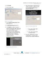
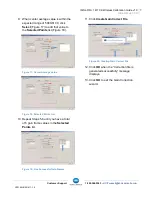
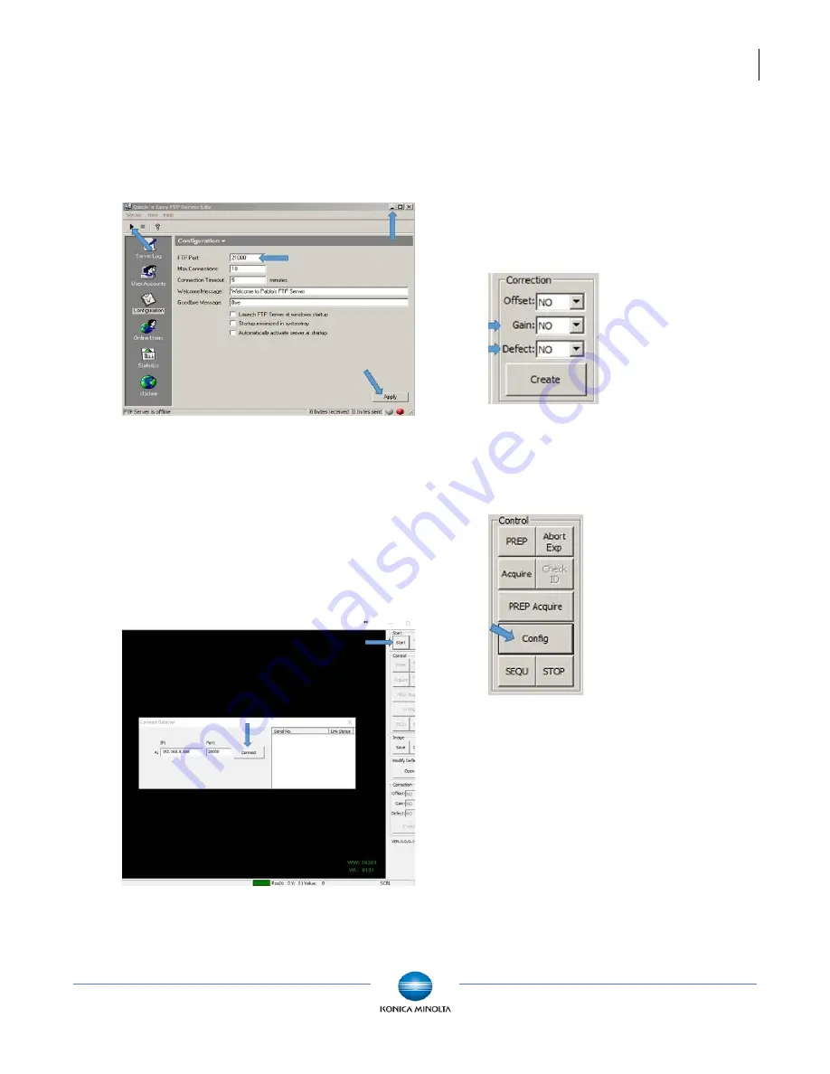
2. Click
Configuration
and change FTP
port to 21000 and click
Apply
.
3. Click
Start
and minimize the FTP Server
window (Do not close).
Figure 7: FTP Utility
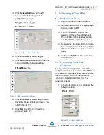
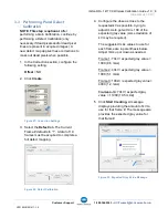
4. Launch the iDemo calibration utility.
a. Navigate to:
c:\IDemo_3.0.0.14
b. Double-click the file,
IDemo_interface.exe
.
5. Click
Start
.
Figure 8: iDemo Connect Detector
6. In the Connect Detector box, click
Connect
(Figure 8).
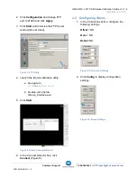
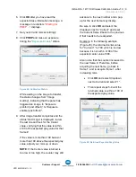
2.2 Configuring iDemo
1. In the Correction section, configure the
following settings.
Offset
= NO
Gain
= NO
Defect
: NO
Figure 9: Correction Settings
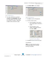
2. Click
Config
to display configuration
settings.
Figure 10: iDemo Settings


