1
1
2
2
TELE
f=25mm
MIDDLE
f=14mm
WIDE
f=8mm
VIVID 9i system
VIVID 9i Measuring area
Positions of digital
camera photos
3D data of reference markers
Scale bar
Reference marker
Coded marker
Measurement with VIVID 9i
Scanning the target with a laser beam
Merging and editing of 3D data
Measure targets of any size.
Konica Minolta employed its expertise in optical engineering to develop interchangeable high-
performance, dedicated lenses. As a result, TELE, MIDDLE and WIDE lenses can be selected to
accommodate the size of the measurement target.
(Input range in X, Y and Z directions: 93 x 69 x 26 mm to 1495 x 1121 x 1750 mm)
Point & Shoot, Leave detailed settings to the 9i.
Konica Minolta's AF/AE technology, developed through its expertise in camera manufacturing,
relieves users from the need to determine the exact measuring distance. Moreover, the system
automatically determines the optimum laser power for the surface conditions of the target.
(Scan Range : standard mode 0.6 to 1.0 m, Extended mode 0.5 to 2.5 m )
Take a measurement with the , Polygon Editing Tool (ver. 2.2 bundled) software.
High speed and high accuracy
Start the measurement by framing the scan area on the LCD
Viewfinder of the VIVID 9i unit or on the host computer’s display .
Each scan requires only 2.5 seconds to aquire accurate 3D data.
Standards-Traceable performance
Konica Minolta supports compliance with ISO 9000. Manufacturers
using VIVID 9i for QC applications can receive test report of the
accuracy of each 9i, traceable to national standard. Thereby ensuring
that our measuring instruments and your process conform to ISO
9000 requirements.
∗
On request, Konica Minolta can provide a test report for each 9i unit. This test
report is created by evaluating the measurement accuracy for all 3 lenses of each 9i
using our Reference 3D Chart, an artifact traceable to national standards, and thus
can be used as documentation for conformance with ISO requirements.
Quick, easy editing
Missed a spot? You’ll see it immediately and be able to scan any
voids. You can check the measured 3D data in real time on the
preview screen. This allows for sequential framing, measurement,
and alignment of the data. Thanks to the improved processing
speed and the new graphical user interface specifically developed
for the VIVID 9i, even large amounts of measurement data can be
merged, edited and converted into general 3D data format with
greater speed and ease. Merging of data can be accomplished by
just clicking on a single pair of points. There is no need to attach
markers, etc. before measurements.
Light-receiving lens (standard accessory)
�
Aluminum Wheel
What’s more, our new field calibration system maintains the high
reliability of the factory settings by canceling the degraded accuracy
caused by lens exchange or a change in environment.
Measurement and data position alignment
PSC-1 Photographing scenario
Merging of 3D data (polygons)
M
ea
su
re
m
en
tF
lo
w
of
V
IV
ID
9i
(P
ol
yg
on
Ed
it
in
g
To
ol
)
Capture the image with a digital camera
Automatic alignment and merging of 3D data
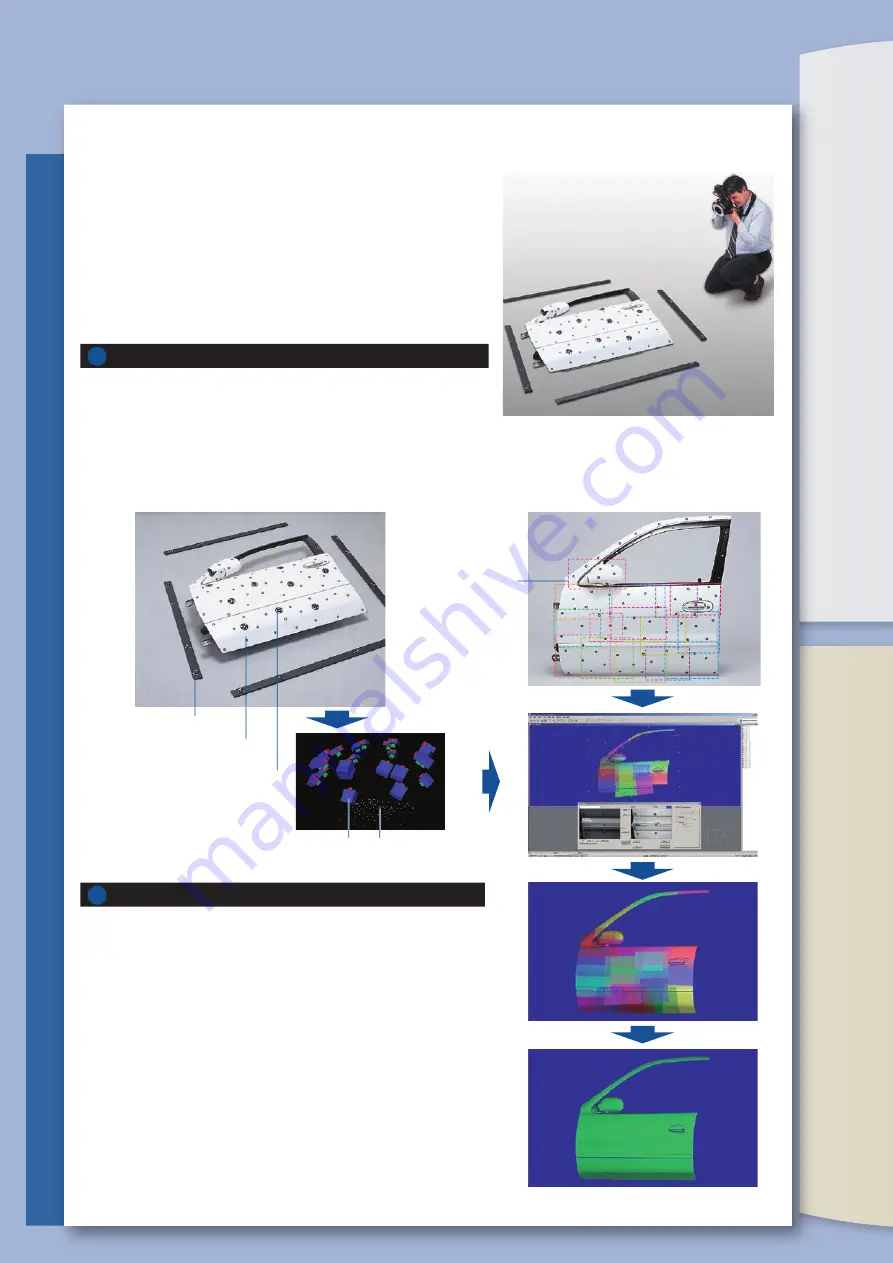
Now it’s time to scan the surface detail using the 9i. As each VIVID 9i scan
is captured, it is automatically aligned to the PSC-1 data cloud created in
step 1. The VIVID 9i reads the target data and places the scans in their
correct orientation. Even relatively smooth shapes such as fenders or
door skins are accurately aligned because the alignment does not depend
on complex surface geometry. Result: a more accurate model.
In addition to being more accurate, PSC-1 saves time. Firstly, any
voids are apparent immediately; aligned data enables the user to scan
any missing surface data. Secondly, since the scans are aligned to the
photogrammetric point cloud (rather than to each other), there is no
need to overlap scans. Furthermore, if two areas of interest are
separated by an unimportant area, the operator no longer needs to
scan the intervening area, saving more time.
The user will place scale bars around the object to be scanned (the
“subject”) and attach reference markers to the subject. With the dedicated
digital SLR, the operator takes pictures of the subject, being sure to include
both the coded markers and dimension-controlled scale bars . Based on
these pictures, the coordinates of the reference markers are determined
with high accuracy using photogrammetric technology, creating a sparse
point cloud of the subject (i.e., a 3D “Constellation” in the shape of the
subject).
VIVID 9i captures large parts (> 1 meter) easily. When PSC-1 is used with
the 9i, the combination enables the user to capture both high-detail and
large parts. In the past, the alignment of multiple scans was error prone,
making it hard to achieve high-detail and high accuracy on large parts.
PSC-1 automates the registration process, and removes the tolerance
stack-up inherent in best-fit techniques.
When measuring a large part maximum detail is achieved by dividing the
part into several scanned regions. With PSC-1 the individual scans are
aligned (registered) automatically, with higher alignment accuracy than
has been possible before. The procedure is described below:
M
ea
su
re
m
en
tF
lo
w
o
fP
h
o
to
g
ra
m
m
et
ry
Sy
st
em
P
SC
-1
�
Door
VIVID 9i
(Polygon Editing Tool Ver.2.2)
VIVID 9i
(Polygon Editing Tool Ver.2.2)
Photogrammetry System PSC-1
optional
Summary of Contents for VIVID 9i
Page 1: ......


