background image

2/27/2020 5:45 PM

D11


40


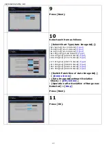
9


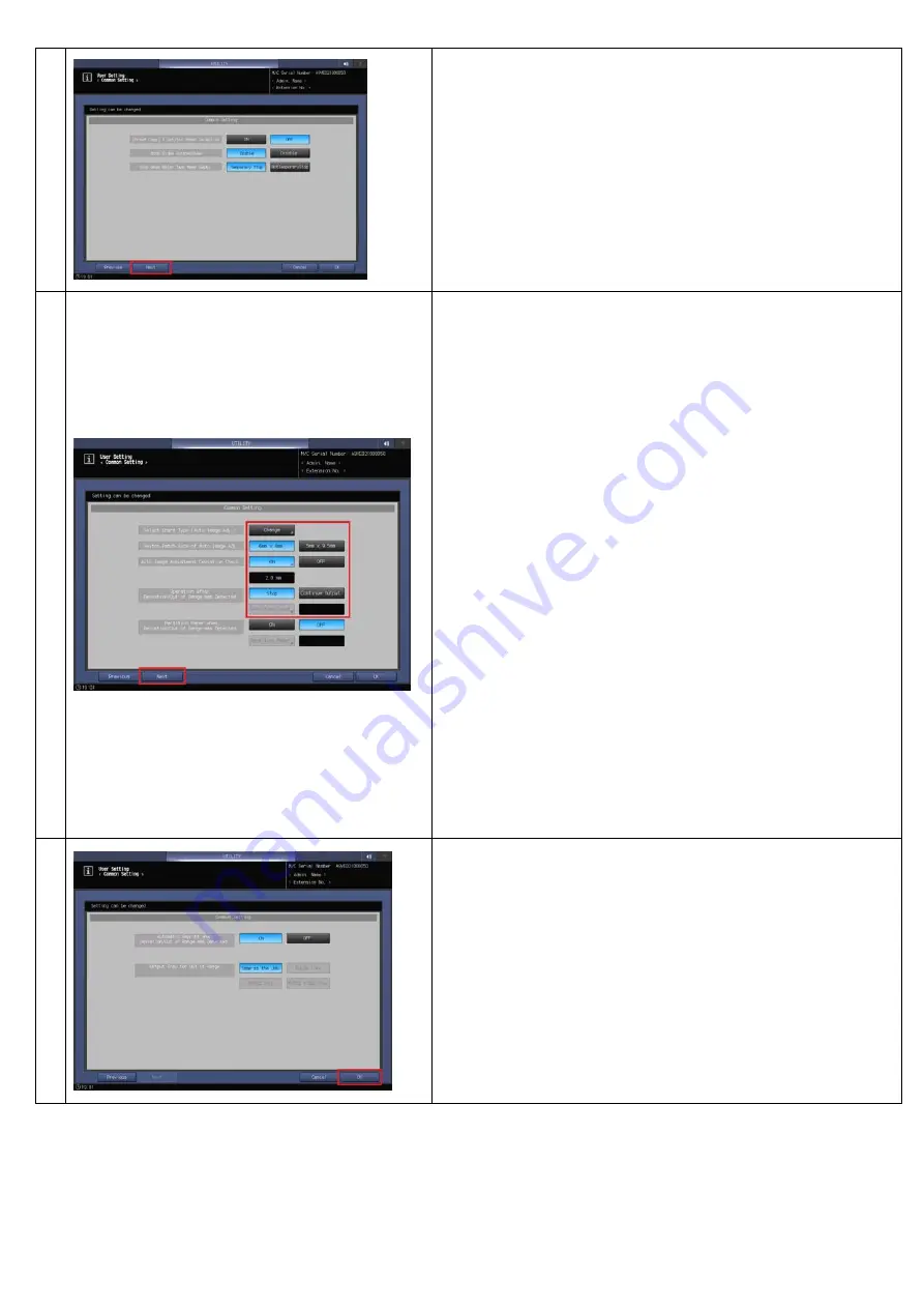
Press [Next].


10


Select each item as follows 
 
- [Select Chart Type(Auto Image Adj.)] 

[62-74g/m2]/[16-19 lb Bond]:

[Type1]


[75-80g/m2]/[20-21 lb Bond]:

[Type1]


[81-91g/m2]/[22-24 lb Bond]:

[Type1]


[92-105g/m2]/[25-28 lb Bond]:

[Type1]


[106-135g/m2]/[29-36 lb Bond]:

[Type1]


[136-176g/m2]/[37-47 lb Bond]:

[Type1] 


[177-216g/m2]/[48-57 lb Bond]:

[Type2]


[217-256g/m2]/[58-68 lb Bond]:

[Type2]


[257-300g/m2]/[69-81 lb Bond]:

[Type2]


[301-350g/m2]/[82-93 lb Bond]:

[Type2]


- [Switch Patch Size of Auto Image Adj.] 
 > [

6mm x 8 mm

- [Auto Image Adjustment Deviation 
  Check] > [

ON/2.0 mm

- [Operation after Deviation of Range was 
Detected] > [

Stop


Press [Next].


11


Press [OK].


Summary of Contents for Color Care IQ-501

Page 1: ...IQ 501 Quick Guide KONICA MINOLTA...

Page 2: ...f Auto Image Adj Settings Step 2 11 Package color auto adj incl Color Density Control Step 12 17 Both side adjustment Step 18 30 Setting Summary p 38 p 46 3b Keep registration and constant color repro...

Page 3: ...please consult with service representative In general coated paper is recommended since color and density reproduction are stable Load the paper actually used for the job into the tray 2 Tray is an ex...

Page 4: ...nistrator Password screen is displayed enter the administrator password using 8 to 64 one byte characters then press OK The administrator password must be specified using 8 to 64 one byte characters 5...

Page 5: ...2 27 2020 5 45 PM D11 4 7 Press Quality Adjustment 8 Press Custom Screen 9 Select Dot190 for Screen1 Press OK 10 Press Exit...

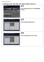
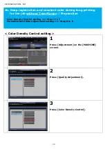
Page 6: ...2 27 2020 5 45 PM D11 5 11 Press Adjustment on the MACHINE screen 12 Press Quality Adjustment 13 Press Color Density Control 14 Press Basic Setting...

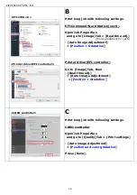
Page 7: ...ty Control ON Periodical Adj Execution ON Adjustment Execution timing During Job Runs Chart Tray Setting OFF Press Next 16 Select each item as follows Adjustment Interval ON Press Change and set 1000...

Page 8: ...not displayed even IQ 501 is equipped please contact your service representative 19 Press Basic Setting 20 Select each item as follows DetailedDiagnosis Sync SimpleDiagnosis ON Detailed Diagnosis Resu...

Page 9: ...creen1 Auto Selection OFF Gamma Auto Adj ON Dens BalanceAdj ON Max Density Adj ON Color Density ON Exact Color or G7 Calibration ON Exact Color Number of Output Job 1 or G7 Calibration Number of Outpu...

Page 10: ...Max density adjustment paper is loaded into the tray 1 as an example 26 Select each item as follows Adjustment Tray Tray2 Auto Run OFF Overwrite Tray Set of Max DensityAdj ON Press OK The paper actua...

Page 11: ...item as follows For KM controller Screen of Adjustment Target Screen1 Auto Selection ON Gamma Auto Adj ON Dens BalanceAdj OFF Max Density Adj ON Color Density ON Exact Color or G7 Calibration OFF For...

Page 12: ...ent Tray Tray2 Auto Run ON if the print engine is turned ON and OFF every day Auto Run OFF if the print engine is running through the days and not turned OFF in daily use Overwrite Tray Set of Max Den...

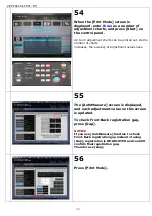
Page 13: ...eDiagnosis ON Detailed Diagnosis Result Auto Reset ON Output Stored Job after Diagnosis OFF Package Color Auto Adj Screen of Adjustment Target Screen1 Auto Selection ON Gamma Auto Adj ON Dens BalanceA...

Page 14: ...ch turned on the Power LED on the control panel lights up in orange 2 Turn ON the sub power switch 3 The Wake up screen is displayed 1b Daily Care Execution Package Auto Color Adjustment If the print...

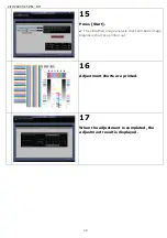
Page 15: ...2 27 2020 5 45 PM D11 14 4 The Package Auto Color Adjustment screen and Warm up screen are displayed 5 Automatically adjustment starts 6 Adjustment charts are printed...

Page 16: ...1 15 Manual Execution 7 Press Adjustment on the MACHINE screen 8 Press Quality Adjustment 9 Press Package Color Auto Adj 10 Press Start The simplified image analysis chart and basic image diagnosis ch...

Page 17: ...2 27 2020 5 45 PM D11 16 11 Adjustment charts are printed 12 When the adjustment is completed the adjustment result is displayed...

Page 18: ...nobs 2 pieces on front and rear side counterclockwise to loosen them 3 While pushing the side guide lock release lever slide the side guide plate outward 2 Adjust registration for new paper Execution...

Page 19: ...e it to the left side Be careful not to move the rear guide plate by force otherwise it may be damaged 5 Load paper so that the stack of paper is aligned against the right side of the tray NOTICE Do n...

Page 20: ...NOTICE Be sure that the rear guide plate is securely aligned to the paper If any gap is left between the rear guide plate and paper the machine cannot detect the correct paper size and machine trouble...

Page 21: ...iden the side guide plates and rear guide plate while pressing the lock release lever of each guide plate NOTICE When moving the side guide plates be sure to hold the lock release lever of the front o...

Page 22: ...is completed the Amount indicator of the tray changes to on the MACHINE screen and COPY screen Withdrawing the tray at this point you will find that the tray bottom plate has been elevated to the top...

Page 23: ...align it to the edge of the paper NOTICE Do not load above the limit level indicated on the side guide plate of the tray Also carefully load paper not to block the air nozzle Be sure that the rear gui...

Page 24: ...he lock release lever of the front side guide plate move the front and rear side guide plates closer until they stop 22 Open the small size guides provided for each of the front and rear side guide pl...

Page 25: ...oad above the limit level indicated on the small size guides Be sure that the rear guide plate is securely aligned to the paper If any gap is left between the rear guide plate and paper the machine ca...

Page 26: ...de plate while pressing the lock release lever of each guide plate NOTICE When moving the side guide plates be sure to hold the lock release lever of the front one and the handle of the rear one If mo...

Page 27: ...ps Otherwise the later operation may be affected because the bottom plate is not elevated completely to the top 31 Adjust the position of the top edges of the side guide plates Move top edges of the s...

Page 28: ...lso carefully load paper not to block the air nozzle Be sure that the rear guide plate is securely aligned to the paper If any gap is left between the rear guide plate and paper the machine cannot det...

Page 29: ...rawn at a time 36 Open the small size guides provided for each of the front and rear side guide plates NOTICE Leave the fixing levers of the paper control panels in the fixed position If you slide the...

Page 30: ...fix the small size guides 39 Align the rear guide plate to the paper Pushing the lock release lever align the rear guide plate to the paper NOTICE Do not load above the limit level indicated on the sm...

Page 31: ...tomatically goes down NOTICE Without the main body power turned on the tray bottom plate does not move down Be sure to turn the sub power switch ON LU 202m LU 202XL XLm 42 Adjust the position of side...

Page 32: ...e the two side guide plates left to an appropriate position according to the size indication provided on the top of the guide plates LU 202m LU 202XL XLm 44 Turn the two side guide fixing knobs of the...

Page 33: ...e rear guide plate to an appropriate position according to the size indication provided on the tray bottom plate Turn the two side guide fixing knobs of the rear guide plate clockwise to fix the guide...

Page 34: ...and 47 until the tray bottom plate will not go down any more NOTICE Do not load above the limit level indicated on the side guide plate of the tray Be sure that the rear guide plate is securely align...

Page 35: ...D11 34 Auto Measure 50 Press Paper Setting on the MACHINE screen 51 Press the tray in which the paper to be adjusted has been loaded Press Change Set 52 Press Both Sides Adj 53 Press AutoMeasure then...

Page 36: ...ber of charts increases the accuracy of adjustment values rises 55 The AutoMeasure screen is displayed and each adjustment value on this screen is updated To check Front Back registration gap press Ga...

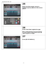
Page 37: ...int Mode screen is displayed press Start on the control panel 58 Check Front Back registration gap If registration gap is not good increase number of adjustment charts and repeat step 53 to 57 again 5...

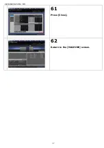
Page 38: ...2 27 2020 5 45 PM D11 37 61 Press Close 62 Return to the MACHINE screen...

Page 39: ...SRA4 SEF can be adjusted automatically For details contact your service representative Confirmation of Auto Image Adj settings default setting 2 Press Utility Counter on the control panel 3 Press User...

Page 40: ...2 27 2020 5 45 PM D11 39 4 Press Common Setting 5 Back Side Magnification Adjustment ON Press Next 6 Press Next 7 Center Crop Mark Trim Margin 1 0 mm Press Next 8 Press Next...

Page 41: ...2 105g m2 25 28 lb Bond Type1 106 135g m2 29 36 lb Bond Type1 136 176g m2 37 47 lb Bond Type1 177 216g m2 48 57 lb Bond Type2 217 256g m2 58 68 lb Bond Type2 257 300g m2 69 81 lb Bond Type2 301 350g m...

Page 42: ...2 27 2020 5 45 PM D11 41 Package Color Auto Adj incl Color Density Control 12 Press Adjustment on the MACHINE screen 13 Press Quality Adjustment 14 Press Package Color Auto Adj...

Page 43: ...PM D11 42 15 Press Start The simplified image analysis chart and basic image diagnosis chart are printed out 16 Adjustment charts are printed 17 When the adjustment is completed the adjustment result...

Page 44: ...43 Both side adjustment 18 Press Paper Setting on the MACHINE screen 19 Press the tray in which the paper to be adjusted has been loaded Press Change Set 20 Press Both Sides Adj 21 Press AutoMeasure...

Page 45: ...ber of charts increases the accuracy of adjustment values rises 23 The AutoMeasure screen is displayed and each adjustment value on this screen is updated To check Front Back registration gap press Ga...

Page 46: ...e Print Mode screen is displayed press Start on the control panel 26 Check Front Back registration gap When registration gap is not good enough increase number of adjustment charts and repeat step 53...

Page 47: ...aper size SRA3 13 x 19 12 x 18 SRA4 SEF Auto Image Adjustment default settings Back Side Magnification Adjustment ON Center Crop Mark Trim Margin 1 0 mm Both Sides Rotate Skew Enable Switch Patch Size...

Page 48: ...o to Quality Tab Auto Image Adjustment Position Gradation Printer driver KM controller Go to Quality Tab then Auto Image Adjustment Position Gradation 3b Keep registration and constant color during lo...

Page 49: ...Real time adj Color gradation for ver 5 Auto Image Adjustment Position Gradation Printer driver EFI controller Go to Image Tab then Real time adj Auto Image Adjustment Position Gradation CREO controll...

Page 50: ...the MACHINE screen 2 Press Quality Adjustment 3 Press Color Density Control 4a Keep registration and constant color during long printing for the job without Trim Margin Preparation Color Density Cont...

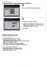
Page 51: ...Color Density Control ON Periodical Adj Execution ON Adjustment Execution timing During Job Runs Chart Tray Setting OFF Press Next 6 Select each item as follows Adjustment Interval ON Press Change an...

Page 52: ...et Deviation Check OFF Press OK Setting Summary of 4a Color Density Control Use Color Density Control ON Periodical Adj Execution ON Adjustment Execution timing During Job Runs Chart Tray Setting OFF...

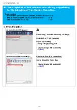
Page 53: ...setting and go to Quality Tab Auto Image Adjustment Off Printer driver KM controller Go to Quality Tab then Auto Image Adjustment Off 4b Keep registration and constant color during long printing for...

Page 54: ...erties and go to Image Tab Real time adj Color gradation for ver 5 Auto Image Adjustment Off Printer driver EFI controller Go to Image Tab then Real time adj Auto Image Adjustment Off CREO controller...

Reviews: