


3. Other
Field Service
V
er. 1.0 Dec. 2007
12
PF-505
Maintenance
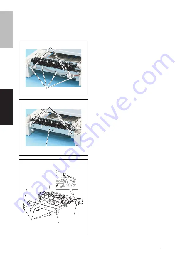
3.3.6
Media feed clutch (CL1)
1.
Remove the Lower Feeder Unit.
2.
Remove the rear cover.
3.
Disconnect three connectors [1] and
remove the harness from four wire
saddles [2].
4.
Remove six screws [1], and remove
the media feed unit [2].
5.
Remove six screws [1], and remove
the sheet metal [2].
6.
Disconnect the connector [3] and
remove the E-ring [4], and remove
the media feed clutch [5].
A0FGF2C004DA
[2]
[1]
A0FGF2C005DA
[2]
[1]
A0FGF2C514DA
[2]
[5]
[4]
[3]
[1]
[1]
Summary of Contents for bizhub 40p
Page 1: ...SERVICE MANUAL 2 2 20 0 00 0 07 7 7 1 1 12 2 2 V V Ve e er r r 1 1 1 0 0 0 FIELD SERVICE...
Page 3: ...ii Blank Page...
Page 23: ...MEASURES TO TAKE IN CASE OF AN ACCIDENT S 20 Blank Page...
Page 26: ...SERVICE MANUAL 2007 12 Ver 1 0 FIELD SERVICE Main body...
Page 183: ...12 Other functions Field Service Ver 1 0 Dec 2007 148 bizhub 40P Adjustment Setting Blank Page...
Page 229: ...18 Wiring diagram Field Service Ver 1 0 Dec 2007 194 bizhub 40P Appendix Blank Page...
Page 230: ...SERVICE MANUAL 2007 12 Ver 1 0 FIELD SERVICE...
Page 233: ...PF 505 General Maintenance Troubleshooting Field Service Ver 1 0 Dec 2007 ii Blank Page...
Page 253: ...4 Jam display Field Service Ver 1 0 Dec 2007 20 PF 505 Troubleshooting Blank Page...
Page 254: ...SERVICE MANUAL 2007 12 Ver 1 0 FIELD SERVICE...
Page 257: ...AD 508 General Maintenance Troubleshooting Field Service Ver 1 0 Dec 2007 ii Blank Page...
Page 259: ...1 Product specifications Field Service Ver 1 0 Dec 2007 2 AD 508 General Blank Page...
Page 275: ...4 Jam display Field Service Ver 1 0 Dec 2007 18 AD 508 Troubleshooting Blank Page...
Page 276: ...SERVICE MANUAL 2007 12 Ver 1 0 FIELD SERVICE...
Page 279: ...SF 603 General Maintenance Troubleshooting Field Service Ver 1 0 Dec 2007 ii Blank Page...
Page 281: ...1 Product specifications Field Service Ver 1 0 Dec 2007 2 SF 603 General Blank Page...
Page 291: ...3 Other Field Service Ver 1 0 Dec 2007 12 SF 603 Maintenance Blank Page...
Page 297: ...THEORY OF OPERATION SERVICE MANUAL 2007 12 2007 12 Ver 1 0 Ver 1 0...
Page 299: ...ii Blank Page...
Page 319: ...MEASURES TO TAKE IN CASE OF AN ACCIDENT S 20 Blank Page...
Page 322: ...SERVICE MANUAL 2007 12 Ver 1 0 Main body THEORY OF OPERATION...
Page 333: ...5 Image creation process Theory of operation Ver 1 0 Dec 2007 8 bizhub 40P Outline Blank Page...
Page 358: ...SERVICE MANUAL 2007 12 Ver 1 0 THEORY OF OPERATION...
Page 361: ...AD 508 Outline Composition Operation Theory of operation Ver 1 0 Dec 2007 ii Blank Page...
Page 363: ...1 Product specifications Theory of operation Ver 1 0 Dec 2007 2 Outline AD 508 Blank Page...
Page 368: ...SERVICE MANUAL 2007 12 Ver 1 0 THEORY OF OPERATION...
Page 371: ...PF 505 Outline Composition Operation Theory of operation Ver 1 0 Dec 2007 ii Blank Page...
Page 379: ...4 Operations Theory of operation Ver 1 0 Dec 2007 8 PF 505 Composition Operation Blank Page...
Page 380: ...SERVICE MANUAL 2007 12 Ver 1 0 THEORY OF OPERATION...
Page 383: ...SF 603 Outline Composition Operation Theory of operation Ver 1 0 Dec 2007 ii Blank Page...
Page 385: ...1 Product specifications Theory of operation Ver 1 0 Nov 2007 2 Outline SF 603 Blank Page...
Page 391: ...4 Operations Theory of operation Ver 1 0 Dec 2007 8 SF 603 Composition Operation Blank Page...
Page 393: ...PARTS GUIDE MANUAL JUNE 2010 bizhub 40P A0DX013...
Page 397: ...bizhub 40P DIAGRAM OF MAIN PARTS SECTION...
Page 416: ...DRIVE SECTION P 9 Please refer Page 10 Key 7 for parts described as S or E M1 1 2 bizhub 40P...
Page 424: ...PF 505 P 13 Please refer Page 10 Key 7 for parts described as S or E 1 2 3 bizhub 40P...


