Seatex AIS 100 Instruction Manual, rev. 5
Installation
37
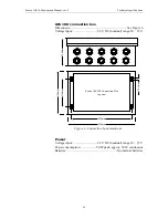
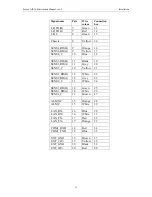
The rear panel contains the connectors for interfacing to external
sensors. The table below describes the type and use of the different
connectors.
Connector
Type
Connected To
Display
9-pin D-Sub male
MKD
Data/power
50-pin D-Sub
Data/power, internal use
GPS
TNC-connector female
GPS antenna
VHF
N-connector female
VHF antenna
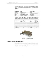
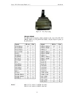
For connecting the MKD unit to the mobile station a D-sub 9 pin
connector is used. The table below shows the wiring of the connector.
Signal name
D-sub 9-pin ref
(male, crimp)
Pair
Wire
colour
Display
connector
(MKD)
Bus-
7
1
Brown
1
Bus+
2
1
White
2
V System -
1
2
Black
4
V
6
2
White
5
Figure 13 The 9-pin D-sub plug
5.4
AIS 100 connection box
When installing the connection box, ensure that there is sufficient
space behind the unit so that cable termination from the mobile station
as well as external sensors can be done properly. Fasten the
connection box to the deck or bulkhead.
Summary of Contents for Seatex AIS 100
Page 1: ...Seatex AIS 100 Instruction Manual...
Page 2: ...Blank page...
Page 4: ...iv Blank page...
Page 8: ...viii Blank page...
Page 20: ...Seatex AIS 100 Instruction Manual rev 5 Operation 12 Blank page...
Page 40: ...Seatex AIS 100 Instruction Manual rev 5 Technical specifications 32 Blank page...
Page 92: ...Seatex AIS 100 Instruction Manual rev 5 External interfaces 84 Blank page...
Page 100: ...Seatex AIS 100 Instruction Manual rev 5 Maintenance 92 Blank page...
Page 104: ...Seatex AIS 100 Instruction Manual rev 5 Troubleshooting 96 Blank page...
Page 106: ...Seatex AIS 100 Instruction Manual rev 5 Parts list 98 Blank page...
Page 110: ...Seatex AIS 100 Instruction Manual rev 5 Appendix B Declaration of conformity 102 Blank page...


