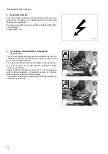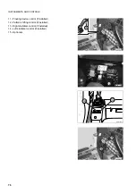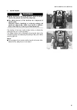
INSTRUMENTS AND CONTROLS
82
OPTIONAL PATTERN CONTROL SYSTEM
CAUTION
q
The procedures to be followed to use any control systems different from the ISO and OPTION PATTER-
NS are described in section "OPTIONAL EQUIPMENT" (See "6.5 HAND & FOOT CONTROL SYSTEM").
Carefully read and be sure to understand the contents of this section before using the machine
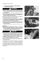
2 - LEFT SERVO CONTROL LEVER (LEFT WHEEL TRAVEL AND LOADER ARM CONTROL)
WARNING
q
Before carrying out any manoeuvre with this lever, the operator must be seated in the work position with
fastened safety belt; before every manoeuvre the operator must take all the precautions indicated in
"3.6.6 HOW TO MOVE THE MACHINE (OPTIONAL PATTERN CONTROL SYSTEM)" and "3.13 USING THE
WORK EQUIPMENT".
q
Before moving, make sure that the parking brake is disengaged.
q
When travelling on roads, always lock the equipment control (see "3.3.5 pos. 8 - EQUIPMENT CONTROL
LOCKING LEVER (IF INSTALLED)".
q
When travelling on roads, make sure that all the safety devices have been engaged.
q
Before leaving the work position, lower the equipment to the ground and lock the safety bars (vertical
position), then stop the engine.
q
Failure to comply with these rules may lead to serious accidents.
CAUTION
q
The self-leveling system is operated automatically only when the loader arm is lifted with loaded bucket.
When the arm is in the lowering phase the system cannot be operated.
q
At the maximum height the self-leveling system keeps the bucket partially folded to prevent the material
from falling out of the bucket itself.
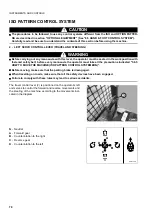
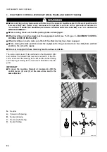
The servo control lever (2) is positioned on the Operator's left
and controls the forward and reverse movements of the ma-
chine, as weel as the steering to the right and the lifting and
lowering of the loader arm according to the movements indica-
ted in the diagram.
IMPORTANT
q
To move the machine forward or backward, shift the
control levers (2) and (3) at the same time and in the
same direction.
RWAA9780
2
RWAA9790
3
Summary of Contents for SK820-5 turbo
Page 2: ......
Page 17: ...SAFETY AND ACCIDENT PREVENTION 15...
Page 19: ...SAFETY NOISE AND VIBRATION PLATES 17 RWA00010 RWA37020...
Page 21: ...SAFETY NOISE AND VIBRATION PLATES 19 RWA37040 RWA00010 RWA00020...
Page 53: ...THE MACHINE AND ITS OPERATIONS 51...
Page 62: ...GENERAL VIEWS 60 10 Left console switches 11 Right console switches RWAA9720 11 RWAA11260 10...
Page 154: ...152 PAGE INTENTIONALLY LEFT BLANK...
Page 155: ...MAINTENANCE 153...
Page 205: ...TECHNICAL SPECIFICATIONS 203...
Page 213: ...TECHNICAL DATA 211 SOLID TYRES SIZE MAKE 10x16 5 AIR BOSS...
Page 214: ...212 PAGE INTENTIONALLY LEFT BLANK...
Page 215: ...AUTHORISED OPTIONAL EQUIPMENT 213...
Page 242: ...240 PAGE INTENTIONALLY LEFT BLANK...
Page 243: ......
Page 244: ...2004 KOMATSU UTILITY EUROPE S p A All Rights Reserved Printed in Europe...


