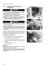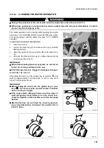
MAINTENANCE PROCEDURE
199
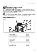
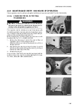
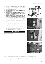
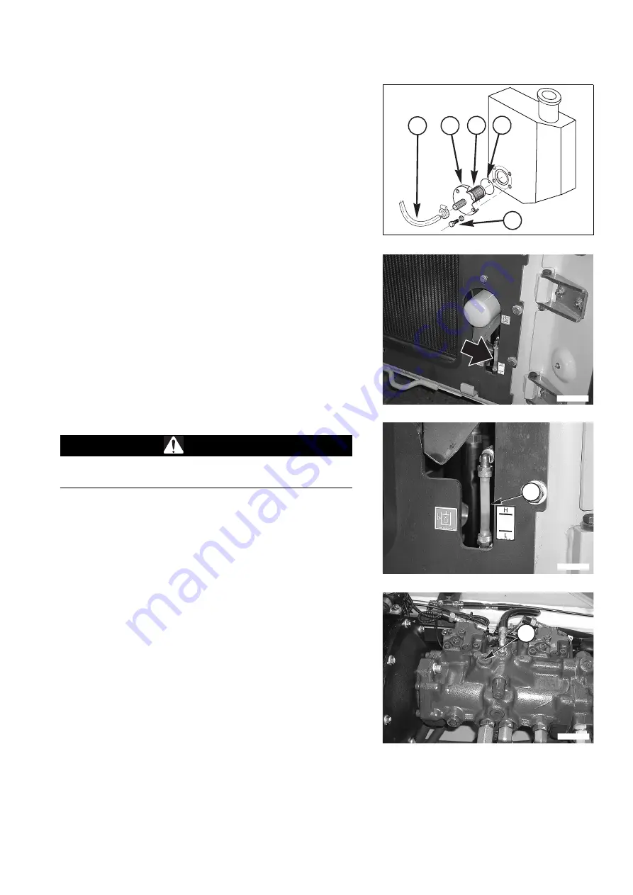
3 - Once the oil has been drained, disconnect the suction
pipe (3) and remove the flange (4) after removing the
screws (5). Use a 17 mm hexagon spanner.
4 - Clean the filtering element (6).
5 - Put back the flange (4), the filter (6), the gasket (7) and
the lower plug (2).
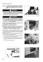
6 - Fill the tank with the prescribed oil until reaching the level
(8). Use only the prescribed type of oil (see "4.3 FUEL,
COOLANT AND LUBRICANTS").
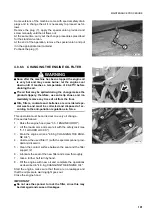
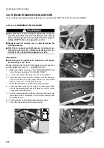
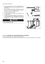
7 - Raise the cab (see "3.5.3.1 RAISING THE CAB") sure
that the oil in the hydraulic pump reaches the maximum
level. To do this, remove the upper plug (9 and make sure
that the hole is completely filled with oil. Use a 1/2” square
section spanner.
8 - If the oil does not reach the maximum level, top up with
the prescribed oil (see "4.3 FUEL, COOLANT AND LU-
BRICANTS").
9 - After the check, lower the cab, screw the filling cap (1),
close the rear panel and the engine hood and deaerate
the system.
10 - Make sure that all the control levers are in neutral position
and let the engine idle for 2-3 minutes before operating
the work equipment.
Move each piston more than once to deaerate the sy-
stem; check again and top up if necessary.
CAUTION
q
Never start the engine with empty tank, since this would
certainly damage the pump.
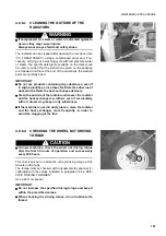
4.8.9.c
CHECKING AND ADJUSTING THE ENGINE VALVE CLEARANCE
Since the check and adjustment of the engine valve clearance require the use of special tools, have these opera-
tions carried out by your Komatsu Dealer.
RWA36400
5
7
4
6
3
RWAA10130
RWAA12570
8
RWAA12580
9
Summary of Contents for SK820-5 turbo
Page 2: ......
Page 17: ...SAFETY AND ACCIDENT PREVENTION 15...
Page 19: ...SAFETY NOISE AND VIBRATION PLATES 17 RWA00010 RWA37020...
Page 21: ...SAFETY NOISE AND VIBRATION PLATES 19 RWA37040 RWA00010 RWA00020...
Page 53: ...THE MACHINE AND ITS OPERATIONS 51...
Page 62: ...GENERAL VIEWS 60 10 Left console switches 11 Right console switches RWAA9720 11 RWAA11260 10...
Page 154: ...152 PAGE INTENTIONALLY LEFT BLANK...
Page 155: ...MAINTENANCE 153...
Page 205: ...TECHNICAL SPECIFICATIONS 203...
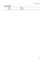
Page 213: ...TECHNICAL DATA 211 SOLID TYRES SIZE MAKE 10x16 5 AIR BOSS...
Page 214: ...212 PAGE INTENTIONALLY LEFT BLANK...
Page 215: ...AUTHORISED OPTIONAL EQUIPMENT 213...
Page 242: ...240 PAGE INTENTIONALLY LEFT BLANK...
Page 243: ......
Page 244: ...2004 KOMATSU UTILITY EUROPE S p A All Rights Reserved Printed in Europe...


