LFO
AND
E
NVELOPE
G
ENERATOR
LFO
The LFO provided on the RH301 is the perfect companion for the clock syncing functions described earlier.
If you have your gear running in sync it gives you an extra CV source that can automatically be synced to
the master clock or a division/multiple of it. The output of the LFO as well as the inverted LFO is 0V – 7.6V.
The LFO has four easy to understand controls:
With the RATE knob you adjust the frequency of the LFO. If it's running in sync mode with the master clock
you can choose between the various divisions and multiples of the master tempo. If the LFO is running in
free mode you can change the frequency continuously from 0.25Hz to 260Hz. The LFO is not intended to
be used as a proper voltage controlled oscillator; it does not respond with 1 octave per volt and in the
higher frequencies the stability is less than 100%.
While the LFO is in sync mode, it will always need one bar in order to adjust to the newly set division after
you haven chosen a new division.
The SHAPE dial lets you choose between the five different waveforms of the LFO: sine, triangle, square,
sample and hold (S&H), and a special waveform which is composed of a sine wave and digital noise.
With the SYMMETRY knob you can bend the waveform. The wave shaping is wavetable based so it will not
be linear for the sine wave and the triangle. For the square wave the SYMMETRY acts like a pulse width
modulation; it ranges from 10% duty cycle to 90% duty cycle. For the S&H output the symmetry adds noise
to the LFO signal. For the “noisine” waveform the symmetry knob changes the noise level.
The SYMMETRY knob has a dent at the 50% setting, so it is easy to find the original, non-shaped waveforms.
Take your time and try the waveforms separately and change the symmetry to get an idea of what you're
changing.
LFO RANGE and SYMMETRY can be modulated by external CVs as well (see Control Voltage Theory
section for more information on that). Please keep in mind that the incoming CV signal (LFO SPEED input)
acts as if you would turn the potentiometer from fully counter-clockwise (CCW) to fully clockwise (CW),
so a rising CV signal from 0V – 5V gets you through the divisions from fast to slow in sync mode but gets
you from a low frequency to the fastest one in Hz mode.
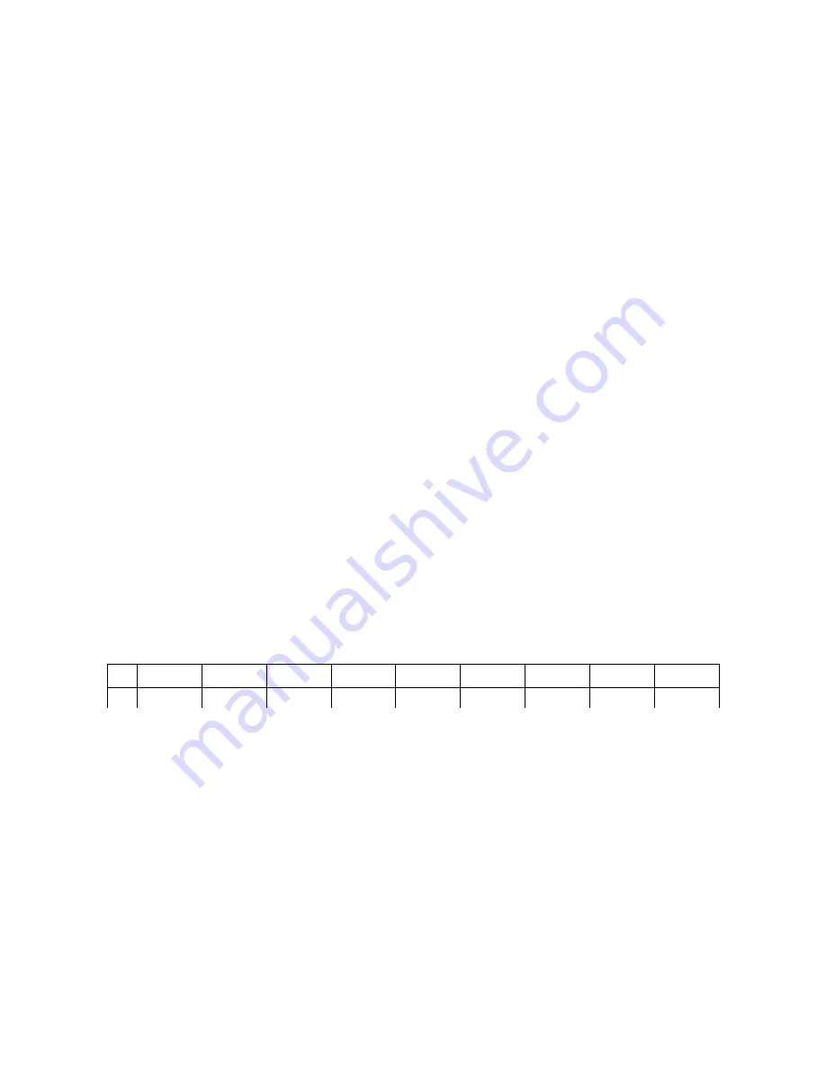
Here is a table for the CV if you want to change your LFO division precisely:
:16
:8
:4
:3
:2
x1
x2
x3
x4
CV
0V– 0.55V
0.56V-1.1V
1.11V-1.65V 1.66V-2.2V
2.21V-2.75V 2.76V-3.3V
3.31V-3.85V 3.86V-4.4V
4.41V-5.0V
Envelope Generator
The RH301 also comes with an envelope generator onboard. For the most part it is a classic ADSR
envelope generator with the addition of the RANGE knob. The RANGE knob is used to scale the time
ranges of the ATTACK, DECAY and RELEASE stages. Simultaneously the behavior of the envelope is
changed from linear to logarithmic. The output of the envelope ranges from 0V – 7.6V.
SUSTAIN is not affected by the RANGE knob as its time is solely affected by the envelope gate. If the
envelope generator is synced to the master clock or the division, the gate is high for exactly 50% of the
corresponding beat.
The RANGE knob scales the time ranges of the attack, decay and release stages from 3ms – 400ms to 40ms
– 4s. At the same time the response curve of the envelope changes gradually from linear to logarithmic, so
you have a snappy linear envelope in the shorter times and a more organic feeling envelope with longer
times.
You can trigger the envelope externally through the ENV GATE input, either with a trigger or a gate signal.
KOMA Elektronik RH301 – Rhythm Workstation / Utility Tool
Page 8


