background image


Vers. 111422


66


USB menu


Tap the USB button from the main menu to enter the USB menu.


From this menu you can save and recall the K-DUCER configuration containing all 
program parameters, sequence parameters, and general settings, from a USB drive 
connected to the USB type-A port on the bottom of the unit.


Note: use the USB type A port for this function, not the mini-USB port.


Note: the USB drive must be formatted with the FAT32 filesystem.


If there is no USB drive connected, or if the USB drive is not formatted with 

FAT32


filesystem, the following screen will appear. Connect a properly formatted USB drive to 
correct this error.


If a properly FAT32-formatted USB key is connected, the load/save/delete buttons will be 
enabled:


Summary of Contents for 033001

Page 1: ...KDU NT and KDS NT Torque range 5 70 cNm 7 100 ozfin OPERATOR MANUAL Patent pending...

Page 2: ...Kg WEIGHT 320 g POWER SUPPLY 100 240 V AC 50 60 Hz POWER SUPPLY 40V DC TENSION 40V DC TENSION 40V DC POWER 12 5 W POWER 12 5 W NOISE LEVEL 70 dB A NOISE LEVEL 70 dB A VIBRATION LEVEL 2 5 m s VIBRATION...

Page 3: ...xposure values and risk of harm experienced by an individual user are unique and depend upon the way the user works the work piece and the workstation design as well as upon the exposure time and the...

Page 4: ...ogram Mode navigation tree 21 Main Screen Program Mode 22 Main Screen Sequence Mode navigation tree 24 Main Screen Sequence Mode 25 Torque and Angle graphing 27 Visualizing the Torque and Angle charts...

Page 5: ...RAMP TIME PV TORQUE menu 50 REV PRE REV menu 53 OTHER menu 54 SEQUENCE SETTINGS menu 57 SEQUENCE SETTINGS menu tree 58 CURRENT SEQ menu 59 GENERAL SETTINGS menu 61 USB menu 66 FREE K EXPAND NT SOFTWA...

Page 6: ...ure that the desired and proper torque is being applied and that the screwdriver motor works efficiently Read the manual carefully and if unsure please contact Kolver for support MODELS KDU NT power s...

Page 7: ...Vers 111422 7 INSTALLATION Installation of KDU NT unit The KDU NT features rubber feet and a tilted screen and can be conveniently set on a flat surface All dimensions are reported in mm...

Page 8: ...Vers 111422 8 Also available separately vertically and horizontally adjustable bracket part number 010401 swivel table stand part number 010402 010401 010402 Connectors...

Page 9: ...Refer to the Retrieving and storing the screwdriving results and USB menu sections USB mini B To connect using K Expand software Refer to the K EXPAND software chapter CN2 male serial connector To con...

Page 10: ...DS screwdriver Lever installation To install the lever kit cod 010450 simply remove the two M2 5 screws from the cover cod 250203 place the lever on top of the cover and screw using the longer M2 5 sc...

Page 11: ...nector out If necessary you can connect and disconnect the screwdriver cable while the KDS NT unit is powered on The KDS NT will recognize a disconnected or recently connected screwdriver and display...

Page 12: ...Vers 111422 12 Reaction arm mounting Example of collaborative robot mounting threaded tool holders also available...

Page 13: ...Vers 111422 13 Threaded M3 fixturing holes side holes on CA models only...

Page 14: ...r if no screwdriver is connected You can still enter the main menu without any screwdriver connected When a screwdriver is connected it will be recognized by the unit and the CONNECTED SCREWDRIVER scr...

Page 15: ...he screwdriver SpeedTargUnderMin Target speed less than the limit allowed for the screwdriver DownshiftTorqueOverTarg The fast phase torque setting is higher than the final target torque DownshiftSpee...

Page 16: ...program is higher than the maximum torque of the screwdriver RevSpeedOverMax The reverse speed is higher than the maximum allowed by the screwdriver RevSpeedUnderMin The reverse speed is lower than th...

Page 17: ...rundown phase Torque rotational force Closing torque the last torque value measured when the screwdriver motor stopped or when the screwdriver lever or remote lever control was released Running torqu...

Page 18: ...of one of the 64 configurable programs 1 to 64 Current program the program currently selected for tightening Program mode in this mode the unit works according the selected program Sequence Job an ord...

Page 19: ...screwdriver will automatically stop according to the configured program in either an OK or a NOK state depending on the success of the tightening The screwdriver will also stop if the lever is releas...

Page 20: ...ghtening direction either via the lever or via remote control Solid purple the screwdriver is running in the de fix direction either via the reverse button or via remote control Blinking purple the re...

Page 21: ...Vers 111422 21 OPERATING THE K DUCER CONTROL UNIT Main Screen Program Mode navigation tree see Torque and Angle graphing for more information...

Page 22: ...main menu 4 Angle value Measured angle value for last screw in degrees 5 Angle target bounds Shows the target angle when in angle control mode or the min max angle bounds when in torque control mode o...

Page 23: ...screw result or error messages ready screw OK screw NOK errors 11 Torque target bounds Shows the target torque when in torque control mode or the min max torque bounds when in angle control mode or ti...

Page 24: ...Vers 111422 24 Main Screen Sequence Mode navigation tree see Torque and Angle graphing for more information...

Page 25: ...in menu 4 Angle value Measured angle value for last screw in degrees 5 Angle target bounds Shows the target angle when in angle control mode or the min max angle bounds when in torque control mode or...

Page 26: ...NOK errors 11 Torque target bounds Shows the target torque when in torque control mode or the min max torque bounds when in angle control mode or timed tightening mode for the current program 12 Torq...

Page 27: ...storing the screwdriving results section for more information Visualizing the Torque and Angle charts To open the Torque and Angle graph screen simply tap the graph icon on the bottom right of the scr...

Page 28: ...the moment the tightening finished The maximum Y Axis tick shown on the Y Axis always corresponds to the maximum torque measured during the tightening In those situations where the maximum torque is...

Page 29: ...in red for NOK results as well The clamping torque in this case refers to the total torque minus the running torque value When the Angle Count STARTING AT setting is set to Ext or to a non zero Torqu...

Page 30: ...ated the tightening reaches its target torque in a fraction of a revolution 30 Examples metal screws on metal socket with simple washer Seating indicates the point at which the underside of the screw...

Page 31: ...owing these guidelines Hard inelastic joints These joints are best finished at low speed to improve precision and avoid a high velocity impact at the end of the tightening Choose a low FINAL SPEED suc...

Page 32: ...ing speed Target torque TC Max torque AC Max angle TC Target angle AC Tightening Tightening speed Target torque TC Max torque AC Max angle TC Target angle AC Post reverse Reverse speed Reverse Torque...

Page 33: ...r The K DUCER will create a folder named as the serial number of the connected screwdriver Inside this folder the K DUCER will save the results of each tightening inside a TXT file The name of the fil...

Page 34: ...S 600rpm Screw count Number of successfully tightened screws total number of screws in program Screw 1 8 Sequence Current sequence and program within sequence program is positional current total Seq...

Page 35: ...male serial connector If using a 2D barcode scanner such as Kolver P N 020051 you must also connect the external power supply included with the scanner The barcode scanner should be configured with t...

Page 36: ...s lifted or if REMOTE PR SEQ is set to SWBX CBS and an incorrect bit is lifted the controller will remain locked Note if you use less than 8 sockets with the CBS880 accessory it is recommended to phys...

Page 37: ...to a consistent amount of closing torque If the running torque value is expected to be higher than the target clamping torque value the application may also require the use of prevailing torque phase...

Page 38: ...easured fall within the bounds while retaining the ability to detect incorrect values Select peak or average VALUE depending on the requirements of the application and shape of the graph If the runnin...

Page 39: ...nish the running torque phase at a higher torque value than the TARGET Torque as the running torque value is not added to the target torque until the end of the running torque window Final test with r...

Page 40: ...uire a prevailing torque phase ending at or after the end of the running torque phase In the RAMP TIME PV TORQUE menu activate the prevailing torque mode with torque and angle Warning for the duration...

Page 41: ...e tightening you can configure a sequence with the Program transition box set to auto The sequence will then transition between two or more programs automatically while the operator continues to hold...

Page 42: ...erent programs 3 Touch to enter the general settings menu to configure general parameters such as passcode lock I O and MODBUS settings kolver accessories language etc 4 Touch to enter the USB menu to...

Page 43: ...up to 64 different programs as well as assign a barcode to each for automatic selection with a barcode scanner Tap the Programs button from the main menu to enter the programs menu Select one of 64 p...

Page 44: ...Vers 111422 44 PROGRAMS menu tree...

Page 45: ...Vers 111422 45...

Page 46: ...Vers 111422 46...

Page 47: ...Vers 111422 47...

Page 48: ...e starting point for the angle measurement at torque threshold at lever pressed or at external signal received 3 TARGET Torque Tap to set the target torque Only available in Torque Control Angle Monit...

Page 49: ...ct Angle Control and Torque Monitoring mode In this mode the screw is tightened down to the target angle number of revolutions of the screw in degrees while the torque is measured 9 TARGET Angle Tap t...

Page 50: ...arget SPEED in the time set If you wish to display an error when the screwdriver reaches target torque or angle during the ramp phase use the 4 MIN TIME function with a timer value equal to the RAMP t...

Page 51: ...The time is counted from the moment the lever is pressed or a remote start signal is received The angle is counted in accordance with the STARTING AT setting This function can be overlapped with the...

Page 52: ...rage VALUE mode the tightening will continue until the running torque window completes and the average value will be checked against the min max bounds If using Peak VALUE mode the tightening will end...

Page 53: ...nctions If you re using an open end wrench attachment the reverse torque should be set to MIN value in order to bring the wrench back to the correct position 4 PRE TIGHTENING REVERSE This function mak...

Page 54: ...AFTER TORQUE phase The TORQUE and ANGLE results displayed at the end of the AUTO REVERSE AFTER TORQUE phase will correspond to the torque angle results from the tightening phase and not those from the...

Page 55: ...ber to the corresponding physical slot 1 through 8 of the Kolver accessory 7 BARCODE Tap to enter the SCAN BARCODE screen to assign a barcode to the current program being edited To be used in conjunct...

Page 56: ...measured when working with the current program is multiplied by this factor For example if a torque value of 3 Nm is displayed with the COMPENSATION setting at 1 but you measure an effective torque va...

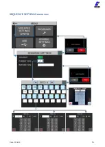
Page 57: ...enter the sequence edit menu for one of 8 sequences A through H The sequence shown in the CURRENT SEQ input field corresponds to the pre selected sequence in the main screen You can also select a dif...

Page 58: ...Vers 111422 58 SEQUENCE SETTINGS menu tree...

Page 59: ...nds The screwdriver will remain disabled until the transition timer completes The timer begins counting as soon as the program is completed even if the lever is not depressed or the remote start comma...

Page 60: ...this transition setting with care and only when strictly necessary as the operator will not have any time to react to the program change 4 Exit Save Key Tap to return to the previous menu and save or...

Page 61: ...ed by the screwdriver Also see MAINTENANCE AND CARE section TEMPERATURE the temperature measured near the motor of the screwdriver in degrees C Note exceeding a temperature of 40 C will put the screwd...

Page 62: ...screen display Choose EXT external to only allow these inputs to be received via external signals on the CN5 connector Choose INT EXT to allow the OK ESC RESET commands from both the touch screen dis...

Page 63: ...appear Then after the first scan the scan PROG barcode screen will appear The program containing the barcode matching the PROG scan second scan will be loaded while the first barcode scanned serial nu...

Page 64: ...e communication protocol to use between the following options K EXPAND to interface with the free K EXPAND PC software via the MiniUSB port MODBUS TCP to interface with any device supporting the MODBU...

Page 65: ...your PC open the windows command prompt and type the following arp 192 168 1 12 a The response will show the MAC address of the K DUCER Alternatively contact your Kolver representative to schedule an...

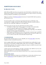
Page 66: ...USB type A port on the bottom of the unit Note use the USB type A port for this function not the mini USB port Note the USB drive must be formatted with the FAT32 filesystem If there is no USB drive c...

Page 67: ...du extension and can be loaded onto this or other K DUCER units or onto the freely available K EXPAND software for PC 3 DELETE programs button Tap to display a list of KDU files found in the root dire...

Page 68: ...Vers 111422 68 USB menu tree...

Page 69: ...iving results as well as torque angle vs time charts in real time at the end of each tightening K Link NT available for KDU NT at a later date K Link is the free software provided by Kolver to automat...

Page 70: ...Open Protocol support will be available at a later date Interface with K EXPAND software via mini USB or ethernet port providing o same functionality available through MODBUS TCP o easiest choice for...

Page 71: ...noisy electrical environments often found in assembly lines Kolver recommends using shielded wires with grounded shields and ferrite beads to limit EMI For these reasons Kolver recommends using the m...

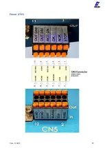
Page 72: ...Vers 111422 72 Pinout CN5...

Page 73: ...exible cable section with min ferrule without sheath mm 0 25 Flexible cable section with max ferrule without sheath mm 0 75 Flexible cable section with min ferrule with sheath mm 0 25 Flexible cable s...

Page 74: ...g completes the screwdriver motor stops and this signal will be ignored until it is pulled down for a recommended minimum of 30ms 4 REVERSE Remote motor reverse start This pin serves the same function...

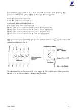
Page 75: ...ample torque reached under minimum time torque reached outside angle bounds etc This signal remains active until the screwdriver changes state again for example when the operator or the PLC initiates...

Page 76: ...ide of any configuration menu Note the K DUCER will respond to the ping command over TCP IP when configured correctly The K DUCER implements a MODBUS server which responds to MODBUS requests The autom...

Page 77: ...e single coil 15 write multiple coils INPUT REGISTERS bytes Data related to the last screwdriving results including closing torque and angle torque angle charts current screwdriving state and errors c...

Page 78: ...CER Series The packet also contains open source scripts to retrieve and store the K Ducer screwdriving results written in PowerShell Python and C that can be used as provided or as a starting point fo...

Page 79: ...quiring or preferring to communicate or control the K DUCER directly using other communication protocols such as PROFINET Ethernet IP or EtherCAT Kolver recommends purchasing a protocol converter such...

Page 80: ...orque elasticity speed of the tightening High torques are defined as above 80 of the maximum nominal torque for the KDS screwdriver model Consider upsizing to a higher torque screwdriver model if most...

Page 81: ...icate the gearbox and checking the calibration of the screwdriver against a certified torque measurement tool Contact your Kolver representative to schedule a maintenance service Alternatively Kolver...

Page 82: ...0619 15 SCREW TSP M3X8 TX10 ZN 16 801009 16 CONNECTOR I O 44PIN 1 872526 17 SCREW M3 X 5 ZN TX10 18 872444 18 CONNECTOR M12 8 POLI FEMALE 1 872537 19 CONNECTOR M16 10 PIN FEMALE 1 201668 HU 20 FLAT CA...

Page 83: ...Vers 111422 83 EXPLODED VIEW KDS NT70 KDS NT70 HM...

Page 84: ...Vers 111422 84...

Page 85: ...Vers 111422 85...

Page 86: ...Vers 111422 86 SPARE PARTS KDS NT70 KDS NT70 HM Lever Kit HM Half Moon model...

Page 87: ...Vers 111422 87 EXPLODED VIEW KDS NT70CA KDS NT70CA HM...

Page 88: ...Vers 111422 88 SPARE PARTS KDS NT70 KDS NT70 HM...

Page 89: ...e free of charge such items This guarantee does not cover repair or replacement required as a consequence of products which have been abused misused or modified or which have been repaired using not o...

Reviews: