


107
105
106
10
- 54 -
FUEL SYSTEM
KD 225_315_350_400_440 Workshop Manual_cod. ED0053029330_
1° ed
_ rev.
00
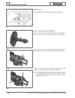
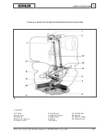
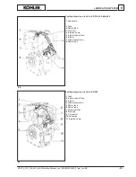
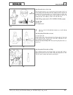
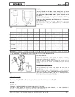
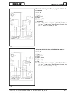
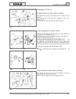
Injection pump components and disassembly
1
Delivery union
2
Filler
3
Spring
4
Gasket
5
Valve
6
Gasket
7
Spring retainer
8
Spring
9
Spring plate
10
Rack
11
Plunger
12
Pin
A
= Fuel outlet union
B
= Fuel intake union
C
= Fastening
D
= Barrel
E
= RH helix
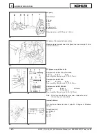
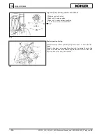
Demount in compliance with the numeric order.
Plate
9
is held firm by pins
12
. Lever up by inserting a tool between
the plate and the body of the pump.
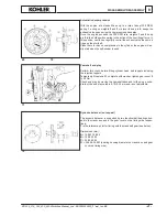
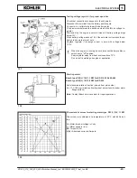
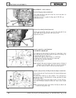
The volume shifted by delivery valve
5
is 15
mm
3
in the pump of KD
315-350 and 25 mm³ in the pump of KD 225 is 21 mm
3
in the pump of
KD 400/440
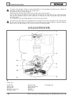
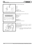
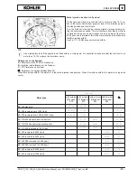
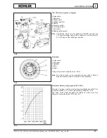
Injection pump, body, plunger and delivery valve
Components:
Dimensions mm:
1
Delivery valve
A
= 5.50 (nominal diam.) 225-315-350
2
Barrel
A
= 7,00 (nominal diam.) 400-440
3
Plunger
A
= 6,00 (nominal diam.) 315-350 EPA
4
Right helix
B
= 2.00 / 2.03
5
Delay notch
C
= 1.50 /1.53
6
Pump body
7
Collar
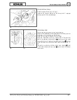
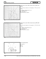
Note:
The injection pump installed in engines for small vehicles,
soundproof generating sets, EPA and KD 400-440 engines,
are characterised by the inclusion of a collar
1
which contribu-
tes to noise-reduction.
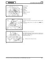
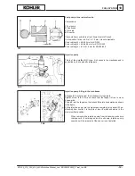
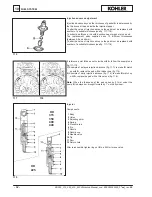
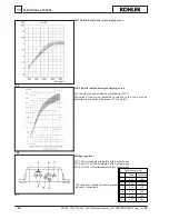
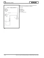
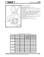
Injection pump refitting
The plunger is fitted with helix
E
facing towards the outlet union
A
;
if it is mistakenly fitted with the helix facing the intake coupling
B
the
injection pump no longer operates (there is no danger of engine ru-
naway); complete refitting following fig. 107.


