8
TT-1686 3/16
Note:
Refer to Figure 11 during kit installation.
13. Install the conversion kit mounting plate
(GM77130). Use seven lock washers (X-22-7) and
seven nuts (X-6210-4) to install the mounting plate
as shown in Figure 11. Install three flat washers
(X-25-122) with three nuts (X-6210-2) as shown.
14. Install the switch cover plate (GM77247) on the
outside of the enclosure door. Use one washer
X-25-122 and nine nuts X-6210-4 to install the
cover plate as shown in Figure 11 and Figure 12.
1
GM99332
1. Switch cover plate mounting hardware
Figure 12
Switch Cover Plate GM77247
Note:
The illustrations in the following steps may not
show the latest controller design. See Figure 13
for the updated current sensing kit terminal block,
harness connection, and programmed-transition
interface board connection.
1. Current sensing terminal block with insulation and harness
(optional)
2. Programmed-transition interface board connection
(programmed- and closed-transition models only)
3. Contactor harness
4. Controller user interface
1
2
3
zab32174
4
Figure 13
Decision-Maker
r
MPAC Controller
Updated Features
Summary of Contents for GLS-1
Page 7: ...TT 1686 3 16 7 Figure 11 Conversion Kit Assembly ...
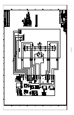
Page 12: ...12 TT 1686 3 16 Figure 20 Current Sensing Kit Wiring Diagram GM47803 ...
Page 17: ...TT 1686 3 16 17 ...
Page 18: ...TT 1686 3 16 18 ...
Page 19: ...TT 1686 3 16 19 ...
Page 20: ...TT 1686 3 16 20 ...
Page 21: ...TT 1686 3 16 21 ...
Page 22: ...TT 1686 3 16 22 ...
Page 23: ...TT 1686 3 16 23 ...
Page 24: ...TT 1686 3 16 24 ...
Page 25: ...TT 1686 3 16 25 ...
Page 26: ...TT 1686 3 16 26 ...
Page 27: ...TT 1686 3 16 27 ...
Page 28: ...TT 1686 3 16 28 ...
Page 29: ...TT 1686 3 16 29 ...
Page 30: ...TT 1686 3 16 30 ...
Page 31: ...TT 1686 3 16 31 ...
Page 32: ...TT 1686 3 16 32 ...


