


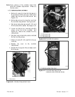


TP-6196 5/04
41
Section 5 Component Testing and Adjustment
5.3 Stator
The stator contains a series of coils of wire laid in a
laminated steel frame.
The stator leads supply AC
voltage to the load and voltage regulator. Before testing
the stator, inspect it for heat discoloration and visible
damage to housing lead wires, exposed coil windings,
and exposed areas of frame laminations. Be sure the
stator is securely fastened to the stator housing.
Note:
Disconnect all stator leads before performing all
stator tests.
Hazardous voltage.
Can cause severe injury or death.
Operate the generator set only when
all guards and electrical enclosures
are in place.
Moving rotor.
WARNING
High voltage test. Hazardous voltage can cause severe
injury or death.
Follow the instructions of the test equipment
manufacturer when performing high-voltage tests on the rotor
or stator. An improper test procedure can damage equipment
or lead to generator set failure.
Short circuits.
Hazardous voltage/current can cause
severe injury or death.
Short circuits can cause bodily injury
and/or equipment damage
.
Do not contact electrical
connections with tools or jewelry while making adjustments or
repairs. Remove all jewelry before servicing the equipment.
Stator Continuity and Resistance Tests
1. Place the generator set master switch in the OFF
position.
2. Disconnect power to the battery charger.
3. Disconnect the generator set engine starting
battery, negative (--) lead first.
4. Disconnect all stator leads before performing all
stator tests.
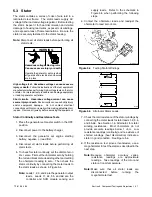
5. To check for stator continuity, set the ohmmeter on
R x 1 scale. First set the ohmmeter zero by holding
the red and black meter leads together and setting
the ohmmeter reading to zero. Then check the
stator continuity by connecting the meter leads to
the stator leads as shown in Figure 5-4.
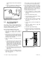
Note:
Leads 1, 2, 3, and 4 are the generator output
leads. Leads 11, 44, 55, and 66 are the
controller and SCR module sensing and
supply leads.
Refer to the schematic in
Figure 5-5 when performing the following
steps.
6. Contact the ohmmeter leads and readjust the
ohmmeter to read zero ohms.
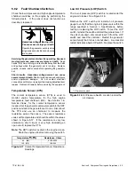
R14807-14
Figure 5-4
Testing Stator Windings
3
4
55
2
1
44
11
6196
66
Figure 5-5
Alternator Stator Leads
7. Check the cold resistance of the stator windings by
connecting the meter leads to stator leads 1-2, 3-4,
and 55-66. See Section 1.6, Alternator, for stator
winding resistances.
Most ohmmeters do not
provide accurate readings below 1 ohm.
Low
resistance readings (continuity) and no evidence of
shorted windings (heat discoloration) indicate a
stator in good condition. See Figure 5-6.
8. If the resistance test proves inconclusive, use a
megohmmeter to test the stator as described in the
next step.
Note:
Because
ohmmeter
accuracy
varies,
resistance
readings
are
approximate
readings. Take readings of the rotor and
stator at room temperature.
Note:
Make
sure
that
all
stator
leads
are
disconnected
before
running
the
megohmmeter test.
Summary of Contents for 12RES
Page 2: ......
Page 24: ...TP 6196 5 04 14 Section 2 Scheduled Maintenance Notes ...
Page 80: ...TP 6196 5 04 70 Section 6 Disassembly Reassembly Notes ...
Page 92: ......
Page 93: ......
Page 94: ......
Page 95: ......


