


TP-6196 5/04
35
Section 4 Controller
4.9 Silicon Controlled Rectifier
(SCR) Module
The silicon controlled rectifier (SCR) module works with
the ADC 2100 to regulate the output voltage.
The
ADC 2100 monitors generator output voltage and
adjusts the excitation current to the rotor through the
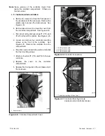
SCR module. The SCR module location is shown in
Figure 4-1.
The SCR module is powered through stator leads 55
and 66 connected to SCR terminals AC1 and AC2.
Leads G connected to terminals G1 and G2 provide the
controller signal. Leads FP and FN connected to the
positive (+) and negative (--) SCR terminals provide
excitation current to the rotor. See Figure 4-16 and the
wiring diagrams in Section 7.
The SCR module is protected by a 20-amp fuse (F1) in
lead 55 in the wiring harness.
Check the fuse and
replace it, if blown.
In the case of output voltage problems, check the
controller configuration and settings. Then test the SCR
module using the following procedure.
SCR Module Test Procedure
Required equipment:
D
Ohmmeter
D
12-volt test lamp (or voltmeter)
D
12-volt DC power source
D
100--500 ohm resistor
D
Jumper
1. Set the ohmmeter to the RX1 scale.
2. Connect the ohmmeter from (+) to (--) on the SCR
module. You should read high resistance in one
direction and low resistance in the other (reverse
the leads).
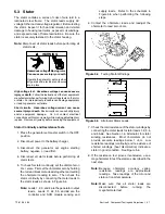
GM28483
G1
G2
AC2
AC1
--
+
Figure 4-16
Silicon Controlled Rectifier (SCR)
Module
3. Connect the ohmmeter from AC1 to (+) on the SCR
module. You should read high resistance in both
directions.
4. Connect the ohmmeter from AC1 to (--) on the SCR
module. You should read high resistance in one
direction and low resistance in the other.
5. Repeat steps 3 and 4 for AC2.
6. Connect the ohmmeter from G1 to (+) on the SCR
module. You should read low resistance in both
directions.
7. Repeat step 6 for G2.
You should read low
resistance in both directions.
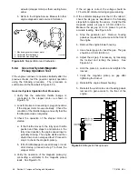
8. See Figure 4-17. Connect the
negative
(--) lead
from the DC power source to the
positive
(+)
terminal on the SCR module.
Note:
The SCR module may be damaged if the
power supply is connected incorrectly. Be
sure to connect the
negative
lead from the
battery to the
positive
terminal on the SCR
module.
1
tp6196
1. 12VDC power source
2. 12 VDC test lamp
3. SCR module
4. Jumper
5. 100--500 ohm resister
G1
AC2
AC1
G2
(+)
(--)
(+)
(--)
2
3
4
5
Figure 4-17
SCR Test
Summary of Contents for 12RES
Page 2: ......
Page 24: ...TP 6196 5 04 14 Section 2 Scheduled Maintenance Notes ...
Page 80: ...TP 6196 5 04 70 Section 6 Disassembly Reassembly Notes ...
Page 92: ......
Page 93: ......
Page 94: ......
Page 95: ......


