background image

G

ENERAL SAFETY NOTES


Page 6 

Version 01-2009


S500K

1  General  safety notes 

1.1 

Possible hazards during interaction with the 

2-wheel tractor 

 
In the case of improper usage or misuse hazards threaten for 


the life and limb of the operator, 


of the 

 2-wheel tractor and other property of the operator, 


the efficient work of the 

-2 -wheel tractor 

 
All persons involved with the commissioning, operation, and maintenance of the  

-2-wheel 

tractor must: 


be accordingly qualified 


observe and follow this operator manual precisely! 


It is a matter of your safety! 


1.2 

Safety notes and hints 
 

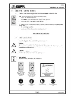
The following symbols are used in this operator manual: 
 

Warning! 

Points out important safety hints in this operator manual. 
When you see this symbol, be aware of possible risks of injury. Read the following note careful-
ly and inform the other operators. 
 

Caution! 

Indicates a possibly dangerous situation. 
Nonobservance of this note could lead to light injuries. 


Information! 

Indicates safety tips and other useful information. 


Wear protective 

glasses 

Wear protective 

gloves 

Wear safety shoes 

Wear hearing protec-

tion 


Before repair, mainte-

nance and cleaning 

work, turn off the engine 

and remove the spark 

plug connector!


Before commissioning, 

read and observe the 
operator manual and 

safety notes! 

Summary of Contents for 4H 500

Page 1: ...eries 500 The basis for working with the 2 wheel tractor is that you read observe and understand this operator manual of the utilized accessory equipment and the engine manufacturer You may not begin operation before doing so Beginning work without observing this manual is prohibited Edition Rev Date 01 2009 11 18 09 Store for future usage Types 4H 500 4K 500 4M 500 ...

Page 2: ...NOTES Page 2 Version 01 2009 S500K Translation of the original operator manual ...

Page 3: ...ct The machine is very stable one can work effortlessly It is equipped with an outstanding engine The maintenance costs are thus very low The gear shift is easy to operate The spare parts supply is guaranteed and occurs quickly An optimal customer service is available to you at all times The 2 wheel tractor has resulted from decades of experience and can therefore be placed into continuous practic...

Page 4: ...ns 14 2 2 Technical data 15 3 OPERATION 16 3 1 Commissioning 16 3 2 Starting 16 3 3 Switching gears in general 17 3 4 Gear switching steering shaft 17 3 5 Shifting fixed shaft 19 3 6 Shifting forward reverse gear on the shaft 20 3 7 Clutch 20 3 8 Power take off 21 3 9 Differential gears 22 3 10 Engine 23 3 11 Gas pedal 23 3 12 Shaft adjustment 24 3 13 Steering shaft optionally for Type 4M standard...

Page 5: ...oundings The 2 wheel tractor Type 4H 500 4K 500 4M 500 may only be used main tained and repaired by persons who are familiar with this and have been instructed about the hazards The 2 wheel tractor may not be used on strongly sloping territory For these special usages there are tool attachments twin wheels iron hanging wheels track widening etc Unauthorized changes to the construction of the 2 whe...

Page 6: ...f your safety 1 2 Safety notes and hints The following symbols are used in this operator manual Warning Points out important safety hints in this operator manual When you see this symbol be aware of possible risks of injury Read the following note careful ly and inform the other operators Caution Indicates a possibly dangerous situation Nonobservance of this note could lead to light injuries Infor...

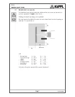
Page 7: ...e hazard zone during work is prohibited This zone begins in the middle of the wheel axle reaches laterally and forwards depending on attachment to various distances with Mowing beam bs 1 m bv 2 m Snow removal sign bs 0 5 m bv 2 m AZM S bs 2 m bv 5 m AZM A bs 25 m bv 25 m Sweeping machine bs 2 m bv 5 m Snow blower bs 25 m bv 25 m Rotary tiller bs 2 m bv 5 m Also observe the operator manuals of the ...

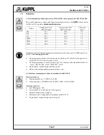
Page 8: ... ex pected wear hearing protection The measurement is made on the lawn outdoors Based on EN ISO 3744 sound power lev el and EN ISO 11201 noise pressure level The measurement device used Norsonic Type 116 conforms to the standard DIN IEC 651 class 1 DIN IEC 804 class 1 DIN 45657 class 1 Engine speed highest engine operating speed Radius of the half shaped measurement surface 4 m 2 Vibrations measur...

Page 9: ...ne and remove the spark plug connector When coupling and decoupling tool attachments to or from the main engine particu lar caution is necessary Make certain that all protective devices are properly installed 1 6 Lighting devices on single axle tractors Here one must differentiate whether the one axled tractor is guided by a pedestrian on the shafts is driven from a seat cart single track trailer ...

Page 10: ...nt of the 2 wheel tractor 1 8 Authorized operators Only authorized persons may work with the 2 wheel tractor The minimum age for operators is 16 years The operator is responsible to third parties in the work area The responsibilities for the various activities on the 2 wheel tractor must be clearly de termined and maintained Unclear competencies are a safety risk The operating company must make th...

Page 11: ...t carrying parts of the ignition system Before starting to drive check brakes and brake effectiveness Remove larger objects from the work area e g boards cables rocks etc Keep hands and feet away from moving parts during operation Ensure sufficient lighting in the work area Work cross wise along the slope never up or down it Be particularly careful when changing the travel direction on the slope N...

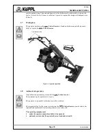
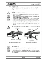
Page 12: ...vice must be brought to a stop with the safety stop lever before the tool is cleaned In the case of machines with a cone clutch 505 506 stop the engine after ending the work and set the clutch to the start position see figure 2 so that the clutch cannot stick due to humidity Deactivating the safety stop lever by binding or taping down is prohibited The protective devices Are installed to protect t...

Page 13: ...llowable axle loads total weights and transport dimensions Check and install transport equipment lighting warning devices protective devices In case of damages stop the machine immediately Remove ignition key if present Have damages repaired After the repair work bring the protective and safety devices back to the protected position Only now is operation again allowed Check the protective devices ...

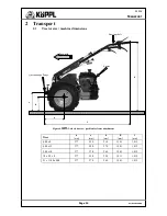
Page 14: ... mm h mm l mm 4 00 x 8 377 220 210 1 191 1 415 4 00 x 12 377 280 270 1 241 1 415 5 00 x 10 377 270 260 1 241 1 415 18 x 9 5 x 8 377 230 220 1 211 1 415 21 x 11 00 x 008 377 270 260 1 241 1 415 Figure 4 2 wheel tractor position for front attachment Steering shaft Forward Engine Quick change flange h a l c d ...

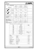
Page 15: ...kg depending on engine type without tires 77 90 120 157 77 140 Differential with block standard standard gear oil SAE 85 W 90 API GL 4 5 SAE 85 W 90 API GL 4 5 SAE 85 W 90 API GL 4 5 Filling quantity gear oil approx 1 7 Ltr approx 1 7 Ltr approx 1 7 Ltr When using a rotary tiller a steering shaft is required Type Engine Version 1 Engine Version 2 505H Diesel Hatz 1B 20 3 6 kW 508H Diesel Hatz 1B 3...

Page 16: ... can be fatal Important During the first 20 operating hours warm up time do not run the engine to the limit of its power capacity After approx 10 operating hours check all screws and operator parts of the basic and attachment devices for tightness 3 2 Starting Warning Activated traction drive and gear box can roll over you and cause serious injuries When starting the engine the traction drive and ...

Page 17: ...ollowing steps Pull the clutch lever Engage parking brake shaft left Select gear Slowly release the parking brake and simultaneously release the clutch similar to driving a car 3 4 Gear switching steering shaft Gear switching front attachment Caution For all gear switching procedures the clutch must always be pulled first B Figure 6 Gear shift in position front attachment Neutral gear mar king LEV...

Page 18: ...ays pull the clutch first use lever C to select the forward or reverse travel direction In the process the following types must be distinguished For type 4M 500 Forward gear Press lever B forwards Reverse gear Pull lever B backwards For type 4H 500 4K 500 Forward gear Pull lever B backwards Reverse gear Press lever B forwards Shifting rear attachment only with steering shaft Caution For all gear s...

Page 19: ... For type 4M 500 Forward gear Pull lever B backwards Reverse gear Press lever B forwards For type 4H 500 4K 500 Forward gear Press lever B forwards Reverse gear Pull lever B backwards Caution The 4th gear may not be used for reverse travel Do not in any case remove the safety device installed for this purpose 3 5 Shifting fixed shaft Differential is activated using a lever on the right shaft Cauti...

Page 20: ...ry af ter a few hours In case the reverse gear can no longer be shifted the setting screw must be slightly loosened Subsequently secure with counter nut 3 7 Clutch Caution Please observe that when shifting the gears for forward and reverse travel and the switching on and off of the implements the clutch must always be pulled The clutch is activated with the clutch handle Pulling the handle causes ...

Page 21: ... take off Warning Before every shifting process of the power take off always pull the clutch The gear independent power take off can be switched off on the 2 wheel tractor The power take off switching is achieved with the gear shift B see figure 12 14 The gear shift B can be recognized by a red handle The switching in the case of tool attachments in the front attachment position by pulling the gea...

Page 22: ...e design with fixed shaft and steering brake the differential lock is operated using a deflection lever on the right side of the shaft see figure 15 Switch on the differential lock during travel Pull the handle for the differential lock until the safety catch latches Switch off the differential lock Pull the handle for the differential lock completely press the safety catch down with your finger w...

Page 23: ...d fuel conserving manner The engine is cooled by means of an air blower The cooling fins of the cylinder are therefore always free of dirt and sucked in plant parts 3 11 Gas pedal The gas pedal is found on the right of the steering shaft see image 17 Please observe the correct setting according to the opera tor manual of the engine manufacturer Speed regulation depending on type of usage Due to no...

Page 24: ...formed Only rotate the shaft when the tractor engine is switched off For the usage of rear tool attachments on the 2 wheel tractor the steering shaft should be rotated 180 without tools For this proceed as follows Pull out the spring cotter pin from the connection joint between the gear change rod and the gear shift on the gear box Afterwards loosen shift rods from connecting joint and pull them o...

Page 25: ...ount on the lower left on the shaft Connect with the connection joint on the power take off lever for gear box and secure with a spring cotter pin Pull the gear change rod for gear shifting A out of the rubber mount on the lower left of the shaft and insert into the rubber mount on the top right Connect with the connection joint for the power take off lever on the gear box and secure with a spring...

Page 26: ...2 downwards to the furthest position and rotate the steering shaft left or right into the desired position Move the steering shaft slightly to the left or right until the locking bolt is detectably latched in the raster Variable steering shaft accessory 20 0 20 20 180 20 3 14 Parking brake brake optional The parking brake is supplied for all 2 wheel tractors The parking brake is operated by the de...

Page 27: ...ing on a slope it is advantageous to keep the differential lock engaged in order to avoid lateral rolling away of the mower Nevertheless a function of the single wheel brake is ensured and the mower treks slightly up the slope Parking braking is achieved by pulling both handles Caution Check the brake function before every trip The braking system must be routinely thoroughly checked Adjustment and...

Page 28: ... long term grease Molyduval see appendix before it is put together Device quick change flange see figure 24 Fast efficient and tool free coupling and decoupling of the tool attachments are achieved using a quick change flange Locking pin latched Figure 25 quick change flange Figure 24 Device connection Lubricating nipple Locking shaft pull up locking pin and rotate 90 Release locking pin Attachmen...

Page 29: ...chine at the workshop and have it adjusted Engine has ignition miss Engine runs in the CHOKE range Ignition cable is loose Fuel line is clogged or contains poor quality fuel Ventilation in the fuel tank cover is clogged Water or dirt is in the fuel system Air filter is dirty Carburetor is out of tune Shift Choke lever to position OFF Insert the spark plug connector firmly in the spark plug Clamp i...

Page 30: ...ngine stop line is defective missing inertia Check and replace line and plug connec tion Engine does not have enough power Cylinder head is loose or the head gas ket is damaged not enough compres sion Have engine checked in the workshop Clutch does not release Clutch slides through Clutch handle is not correctly set Clutch cover is worn Adjust clutch clearance Replace clutch disk Excessive vibrati...

Page 31: ...ety stop lever Function check B Lubricate quick change flange 1 B B B Check and lubricate gear change rod 2 B B B B Check readjust and lubricate Bowden cable 3 B B B B Oil change Gear box First time Then every 4 W W W 33 Oil level check Gear box B B B 32 Check screws and operator parts B B B Tire pressure B B Wheel nut B B B Engine maintenance see operator manual of the respective engine manufactu...

Page 32: ...twist out the oil measurement stick wipe with a clean rag and twist back in Then twist out again and read the oil level if necessary top off with motor oil Always change gear box oil in a timely manner Keep oil fill opening as well as drain screw see figure 26 and 27 and surroundings meticulously clean so that no dirt enters the inside of the gears The oil in the gears should be changed after the ...

Page 33: ...clutch handle should be pulled The clutch is set correctly if the clutch doesn t decouple until the last third of the coupling path see figure 28 After the first operating hour the setting of the clutch must be checked and possibly readjusted Adjustable by means of a setting screw on the clutch handle see figure28 Depending on the usage case the setting screw must be screwed in or unscrewed so tha...

Page 34: ...r a longer period of time then Carry out a thorough cleaning touch up the paint and spray blank parts with corrosion protection oil Preserve engine change the oil by unscrewing the spark plugs and adding 1 2 teaspoons of motor oil to the spark plug opening Slowly turn the engine over several times Screw in the spark plugs Turn over the engine until compression is present valves are closed Turn the...

Page 35: ...ts Size EP2 LS 2 SP GE SP MO Special long term grease lead free lithium emulsified long term grease with EP properties for quick change flange Lubricating grease Gear oil SAE 80W90 API GL 4 5 Motor oil 15W 40 Cartridge 400 g Cartridge 400 g Bottle 1 Liter Bottle 1 Liter Order number Corrosion protection agent Size 170 05 J Fluid D Tube 75 ml 6 2 Accessories Steering shaft Rotor for rotary tiller C...

Page 36: ...uidelines EU guideline machines 2006 42 EG Applied harmonized standards EN ISO 12100 1 EN ISO 12100 2 EN 12733 EN ISO 13857 EN ISO 14121 1 EN 349 EN 709 Applied national standards and technical speci fications Constructive changes which affect the technical data and the intended usage specified in the operator manual which thus significantly change the machine invalidate this decla ration of confo...

Reviews: