K71000 Automatic PMCC Flash Point Analyzer
Operation and Instruction Manual
K71000-Manual
-
13-
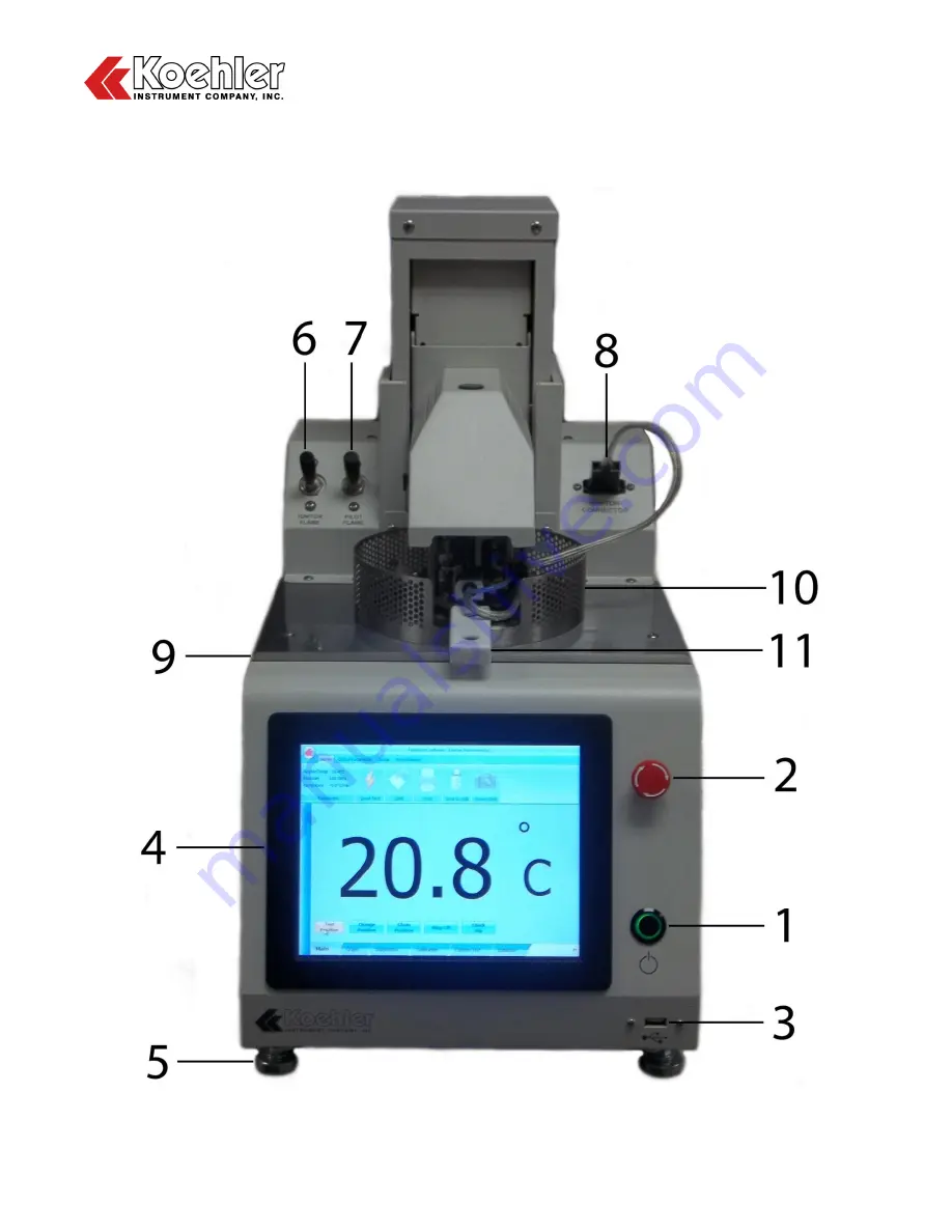
4 Descriptions
4.1
Front of Instrument
Figure 1: Instrument Descriptions_Front
Page 1: ...enue Bohemia New York 11716 1796 USA Toll Free 1 800 878 9070 US only Tel 1 631 589 3800 Fax 1 631 589 3815 http www koehlerinstrument com e mail info koehlerinstrument com Petroleum Testing Analysis...
Page 2: ......
Page 3: ...e statement is given cataloging the items that require separation from the equipment along with basic information on subsequent processing or recycling prior to disposal of the equipment http www dpa...
Page 4: ...As a minimum the following substances preparations and components have to be removed from any separately collected WEEE Mercury containing components such as switches or backlighting lamps compact fl...
Page 5: ...Safety Considerations 8 2 2 Unit Design 8 2 3 Contaminated Samples 9 2 4 Safe Quick Test Method 9 2 5 Fire Detection Suppression and Draft Shield Dome System 9 2 6 Equipment Modification and Replacem...
Page 6: ...ility for losses arising from the negligent or improper use of our equipment nor for losses arising from the improper use or use other than intended Only deliberate action or gross negligence are grou...
Page 7: ...ng needs Our products are backed by our staff of technically knowledgeable trained specialists who are experienced in both petroleum products testing and instrument service to better understand your r...
Page 8: ...The scope of the method covers the analysis of products in the temperature range of 40 to 360 C but this automated apparatus extends the range from dew point 10 C to 400 C Internet Link to Summary AST...
Page 9: ...ange Ambient to 405 C 761 F Flash Detection System Differential Thermocouple Ionization Detection Stirring Speed 0 to 300 RPM Heating Rate In accordance to ASTM D93 procedure A B C Quick Test 12 C min...
Page 10: ...fety problems associated with the use of this equipment It is the responsibility of any user of this equipment to investigate research and establish appropriate safety and health practices and determi...
Page 11: ...prescribed end point prior to running a quick test The set maximum run temperature is solely at the user s discretion We recommend this method of screening for ALL samples 2 5 Fire Detection Suppress...
Page 12: ...emoved WARNING Electrical hazards exist inside the instrument case Lethal voltages and current are present Only factory authorized or otherwise qualified personnel may repair or service this instrumen...
Page 13: ...r claim if requested When submitting a claim for shipping damage request that the carrier inspect the shipping container and equipment Do not return goods to Koehler without written authorization 3 3...
Page 14: ...results outside the above mentioned criteria Ventilation A fume hood or exhaust system is required after performing a test Flammable vapors and or steam are generated during operation and must not be...
Page 15: ...K71000 Automatic PMCC Flash Point Analyzer Operation and Instruction Manual K71000 Manual 13 4 Descriptions 4 1 Front of Instrument Figure 1 Instrument Descriptions_Front...
Page 16: ...load factory software updates 4 Touch Screen Control Panel Main control point of instrument Please refer to section _ _ for full operational details 5 Leveling Feet To make adjustments to instrument l...
Page 17: ...K71000 Automatic PMCC Flash Point Analyzer Operation and Instruction Manual K71000 Manual 15 4 2 Back of Instrument Figure 2 Instrument Descriptions_Back...
Page 18: ...reen control panel 15 USB Port For connection to Keyboard or Mouse 16 RS232 Port For connection to external PC 17 Ethernet Port For connection to LIMS system 18 CPU Port For programming of internal CP...
Page 19: ...etection thermocouple will automatically detect this and initiate re lighting of the flame 27 Pilot Flame The pilot flame ensures the test flame is lit prior to each test dip 28 Electric Ignitor Alter...
Page 20: ...orities Key The fourth or factory level is designed for administrative purposes only and specifically allows for access to the factory settings menu From this screen the user can also Change User Pass...
Page 21: ...t the which operations they want a particular user level to have access to The user can choose to turn on or off access to the Diagnostics Calibration and Custom Test Menus Click Save when complete Fi...
Page 22: ...eset all global parameter settings back to the factory default Figure 7 Last Global Parameter Pop Up 5 Main Home Screen After clicking Yes or No to the Last Global Parameter pop up the user will be br...
Page 23: ...d to a Laboratory LIMS system by clicking this button Print This function is only accessible when the user is in the results database screen Data can be sent to a printer by clicking this button Save...
Page 24: ...dard Test Parameters Change Save minimum temperature in which the instrument lift can open safely and the temperature in which the cooling fan can be turned off Inst ID Setup Change Save Instrument ID...
Page 25: ...Graph Tools The Graph screen features the following functions a Zoom In b Zoom Out c Pan XY Provides cursor that can be moved along graph and display data d Restore Resets X and Y Axis to default posi...
Page 26: ...Dip Home Brings flame dip mechanism to home position b Find Lift Home Brings mechanical lift to Home Position also considered test position c Clean Position Brings mechanical lift to Clean Position h...
Page 27: ...med Two Point Calibration RTD Correction Table User CRM Calibration Two Point Calibration as shown in Figure 14 below is performed using an external PT100 Simulator Box Available as an Additional Acce...
Page 28: ...in which the user can input offset values for any of temperature values shown This table is particularly convenient for those with Certified Digital Contact Thermometers or Certified Liquid in Glass...
Page 29: ...Material CRM samples using a Gas Ignition source 1 Input the certified flash point value from the CRM bottle label or test certificate into the first column titled CRM Flash Value 2 Perform a series...
Page 30: ...erial CRM samples using the Electrical Ignition Source 1 Input the certified flash point value from the CRM bottle label or test certificate into the first column titled CRM Flash Value 2 Perform a se...
Page 31: ...ric Pressure Correction Feature As pictured in Figure 18 below the user can Enter Atmospheric Pressure in Kilopascals kPa into the empty field The Measured Barometric Pressure is determined by the ana...
Page 32: ...C value as pictured in Figure 19 below This method of calibration is useful when a material of known flash point is tested and the analyzer is displaying a value greater than the known value e g know...
Page 33: ...RPM Heating Rate C min End Test Temperature EFP X C Fan Off Temperature C Pre Heat Limit Temperature C Pre Heat Ramp Rate C min Open Lift Temperature C Soak Temperature C Typically used only for Aspha...
Page 34: ...parameter data will automatically be sent to the database Each test is listed in a single row with the information separated by column The user also has the option to delete or update the database lis...
Page 35: ...and clicking on the Print button will cause a temporary Print Result Screen to appear followed by a Printer Options Menu See Figures 22 and 23 below Once the appropriate printer is selected click the...
Page 36: ...n the user first enters this menu the display screen will be blank Clicking on the Monitor Traffic box will begin displaying the data communication At this time a screenshot can be taken of the curren...
Page 37: ...for a Test Dip The Dip On Off Switch will activate or deactivate the dipping mechanism b Adjust Lift Mechanism Pressing the Up and Down Arrows will adjust the level at which the Lift Mechanism will b...
Page 38: ...d See Figure 26 below The corrected flash point value is prominently displayed at the center of the screen Additionally the Type of Ignition used to perform the test is displayed as well as the Sensor...
Page 39: ...authorize the return of the product to the factory The sole responsibility of Koehler Instrument Company and the purchaser s exclusive remedy for any claim arising out of the purchase of any product i...
Page 40: ...K71000 Automatic PMCC Flash Point Analyzer Operation and Instruction Manual K71000 Manual 38 Notes...
Page 41: ...K71000 Automatic PMCC Flash Point Analyzer Operation and Instruction Manual K71000 Manual 39 Notes...
Page 42: ...K71000 Automatic PMCC Flash Point Analyzer Operation and Instruction Manual K71000 Manual 40 Notes...