background image

Chapter 6 Data backup and Initialization                                                 

KGP-922 


6-4                                                                                                                             


            0093130022-00 

6.2  Initialization 

When some malfunction of Display unit is found, following initialization procedure may be required. It 

returns all the settings in the menu to the factory settings.   

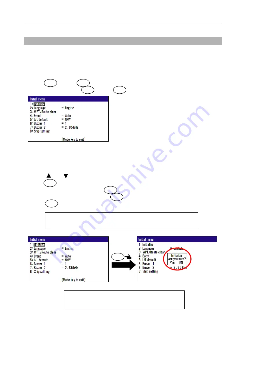
6.2.1    Displaying the 

“Initial menu”


The procedure is as follows: 

(1) Press                key and                key, and Power ON.


(2) Release your finger from                key and                key when opening screen appears. 


6.2.2    Initialize 

Before initializing please note all system parameters and reset them after initialize, or backup for setting 

value in USB memory. (Refer page 6-2) 

(1) Press [        ] or [        ] key to move cursor o

nto the “

Initialize

”. 

(2) Press                key. 

(3) Select 

“Yes” in the pop-up and press                key. 

(4) Select language in the pop-up and press              key.   

(5) Press                key to exit initial menu. 


MENU 

ENT 

MENU 

ENT 

ENT 

ENT 

NOTE: If you want to go back up for before initialize, 
            please write setting value of USB memory. 
            Refer page 6-2 


ENT 

MODE 

NOTE: Already registered data on the waypoints, events, POBs and routes 

remain unchanged.


Press 

ENT 

Summary of Contents for KGP-922

Page 1: ......

Page 2: ......

Page 3: ...dicated at the lower right side on the cover and at the left or right side of the footer region of each page 2019 Koden Electronics Co Ltd All rights reserved No part of this publication may be reproduced transmitted translated in any form by any means without the written permission of Koden Electronics Co Ltd The technical descriptions contained in this publication are subject to change without n...

Page 4: ... and some parts may be omitted Koden is not liable for damages and troubles arisen from misunderstanding of the contents in this manual Koden is not liable for any damages caused by earthquake lightning wind and flood damage and fire for which Koden is not responsible and actions by third parties other accidents customer s unintended error abuse and the use under other abnormal conditions Koden is...

Page 5: ...en after the power is switched off To prevent contact with the high voltage circuits accidentally a protective cover or the label with this mark is provided on the high voltage circuit When the inside is to be checked ensure to switch off the power and to discharge the residual voltage for safety An engineer authorized by Koden shall carry out the inspection and maintenance works Power off in the ...

Page 6: ...electric shock In case of failure please contact Koden s dealers or Koden In case of smoking or firing switch off the power in the boat and of this equipment It may lead to firing electric shock or damages Be careful of residual high voltage High voltage may remain in capacitors for several minutes after switching off the power Before inspection of the inside please wait at least 5 minutes after s...

Page 7: ...ta display3 NAV3 screen Nav data3 mode 1 4 1 4 5 Navigation Graph display NAV4 screen Navigation Graph mode 1 4 1 4 6 Highway display NAV5 screen Highway mode 1 5 1 4 7 Plotter display NAV6 screen Plotter mode 1 5 1 5 Storing present position EVENT 1 6 1 5 1 AUTO 1 6 1 5 2 MANUAL 1 6 1 5 3 Changing the setup contents 1 7 1 6 Using POB People over board 1 8 1 7 Recalling Event and POB position 1 8 ...

Page 8: ... 4 5 Erasing a single route 2 14 2 5 Route setup 2 15 2 5 1 Selecting route navigation 2 15 2 5 2 Checking a route point position 2 16 2 5 3 Canceling route navigation 2 17 2 5 4 Switching between distance and time to go 2 17 2 6 Setting an anchor position 2 19 2 6 1 Storing an anchor position 2 19 2 6 2 Canceling anchor position 2 20 2 7 Track display 2 21 2 7 1 Display a cross cursor on NAV6 scr...

Page 9: ...the DGPS input signal baud rate 4 10 4 3 8 Beacon monitor 4 11 4 4 Menu 5 Compensation 4 12 4 4 1 Correcting your position 4 12 4 4 2 Disable position correction 4 13 4 4 3 Compensating the LOP 4 13 4 4 4 Compensating the compass 4 15 4 4 5 Displaying local time 4 16 4 5 Menu 7 Calculation 4 17 4 5 1 Calculating the distance and bearing between two points 4 17 4 5 2 Calculating LOPs based on LAT L...

Page 10: ...1 5 2 Storing waypoints LOPs data 5 4 5 2 1 Storing a new position or updating an existing one 5 4 5 3 Compensating the LOP 5 5 5 4 Calculating LOPs based on LAT LONG data 5 5 Chapter 6 Data backup and Initialization 6 1 6 1 Data backup 6 1 6 1 1 Displaying the Data backup menu 6 1 6 1 2 Insert USB memory 6 1 6 1 3 Read out of data 6 1 6 1 4 Writing of data 6 2 6 2 Initialization 6 4 6 2 1 Display...

Page 11: ...requirements 8 2 8 1 3 Compass safe distance 8 2 8 1 4 Environmental conditions 8 2 8 2 External dimensions and weight 8 3 8 2 1 External dimensions and weight of the Display unit KGP 922 MU 8 3 8 2 2 External dimensions and weight of the Antenna unit GA 09 8 3 Chapter 9 Maintenance and Troubleshooting 9 1 9 1 Periodic inspection and cleaning 9 1 9 1 1 Monthly check 9 1 9 1 2 Maintenance 9 1 9 2 T...

Page 12: ...his unit are as follows KGP 922 consists of two main components Display and Antenna Display unit has processor receiver and LCD display built in KGP 922 has high resolution color LCD of high brightness type KGP 922 can support DGPS by connecting an external beacon receiver Also support DGPS by SBAS Satellite Based Augmentation System KGP 922 can storage 5 000 waypoints 100 routes and 3 000 track p...

Page 13: ...M CW 376 5M Marine radar Chart Plotter Echo sounder Auto pilot DATA 1 Connector CW 373 5M CW 376 5M CW 276 2M Owner supply Option Standard configuration Legend POWER Connector Marine radar Chart Plotter Echo sounder Auto pilot Black Red Display unit KGP 922 With mounting bracket and cover HUB Ethernet equipment DATA 2 Connector CW 376 5M Beacon receiver ...

Page 14: ...t Plotter Echo sounder Auto pilot DATA 3 Connector CW 376 5M Marine radar Chart Plotter Echo sounder Auto pilot DATA 4 Connector CW 376 5M Marine radar Chart Plotter Echo sounder Auto pilot DATA 1 Connector CW 376 5M Display unit KGP 922 With mounting bracket and cover DATA 2 Connector CW 373 5M CW 376 5M Marine radar Chart Plotter Echo sounder Auto pilot CW 376 5M DATA 2 Connector CW 376 5M Junct...

Page 15: ...t mount 0 68kg 02 Connecting cable CW 373 5M 6 pin water resistant connectors both ends 5m 03 CW 376 5M 6 pin water resistant connector and other end plain 5m 04 Junction box JB 35 1 input 3 outputs with CW 376 5M 05 Hose band 738 1015 2pcs for antenna fixture 06 Power rectifier PS 010 With 5A fuses 2pcs 3 5kg 07 AC power cable VV 2D8 3M For PS 010 both ends plain 3 m 08 Antenna cable extension ki...

Page 16: ... This page intentionally left blank ...

Page 17: ...Recalls memory position entry of numerical values and selection North or South latitude or East or West longitude Selects NAV1 NAV2 NAV3 NAV4 NAV5 or NAV6 screen Recalls the menu Clears numeric optional parameter or stops alarm sound temporarily Enters a numeric optional parameter Turns the power on Press and hold the power OFF Changes the brightness Activates POB People Over Board function ...

Page 18: ...f check Press until Power off 3sec is displayed for turn NAVIGATOR off All data before power off is kept in memory for later use NOTE This setup is memorized and turns into the same setup next time at the time of a power supply ON BRILL BRILL CAUTION Be sure to turn off the power in the above procedure Press to change the LCD brightness in 7 levels After the popup of below was displayed push the k...

Page 19: ...c key on the upper left corner of the screen 2 Press key to select the display mode 1 4 2 Nav data display1 NAV1 screen Nav data1 mode MODE MODE MODE MODE MODE MODE Nav data display1 Nav data display2 1 2 N 3 4 W 5 6 E Nav data display3 Navigation Graph display Highway display Plotter display RAIM Receiver autonomous integrity monitoring Speed Over Ground Course Over Ground Position in latitude an...

Page 20: ... screen Nav data3 mode 1 4 5 Navigation Graph display NAV4 screen Navigation Graph mode Course Over Ground Position in latitude and longitude Speed Over Ground Course Over Ground Position in latitude and longitude Course Over Ground Speed Over Ground Speed Over Ground Range ring Range Heading Line Position in latitude and longitude ...

Page 21: ...hway mode 1 4 7 Plotter display NAV6 screen Plotter mode Course Over Ground Course Over Ground Speed Over Ground Position in latitude and longitude XTE alarm range Cross Track Error Course Deviation Angle Speed Over Ground Range Own boat mark Heading Line Position in latitude and longitude ...

Page 22: ...VT key does not function when positioning is invalid 1 Press key to appear the pop up 2 Press key to store your present position 3 You can store up to 999 present positions by pressing this key They have storage numbers 0001 to 0999 1 Press key to show the registration number display window 2 Press key to store your present position 3 Specify a desired registration number by numeric keys 4 Press k...

Page 23: ... to select 10 Plotter 3 Various settings 1 1 Mark symbol Press key To change the Mark symbol place cursor on SYMBOL option and press ENT key 2 2 Mark display Press key You can select whether or not to display the POB mark information 2 N 1 MENU 0 Initial setup Green Key board cursor Select symbol Press ENT Initial setup Symbol Number Press ENT ...

Page 24: ...ode and returns to the previous screen when you pressed POB key When alarm sounds press CLR key to stop it Press it again to return to the screen you were at before you pressed POB key NOTE 000 Position data where you pressed POB key 0001 to 0999 Position data that contains events 1 Press key to appear the pop up 2 Press key to store POB position POB EVT POB POB MENU 1 POB appears Proximity alarm ...

Page 25: ...0999 by numeric keys 7 Press key to copy the storage data 1 8 1 Erasing Event and POB position 1 Press key until Menu options 1 to 10 appears 2 Press key to select 1 Waypoints 3 Enter storage number 0001 to 0999 by numeric keys and press key 4 Press key to display the pop up 5 Select Delete in the pop up and press key 6 If OK select Yes in the pop up and press key If cancel erasing select No in th...

Page 26: ...Chapter 1 Basic Operation KGP 922 1 10 0093130022 00 Press ENT ...

Page 27: ...to 4999 total of 4000 points to store waypoints 1 Press key until Menu options 1 to 10 appears 2 Press key to select 1 Waypoints 3 Enter storage number 0000 to 4999 by numeric keys and press key 4 Press key to display the pop up 5 Select Edit in the pop up and press key MENU 1 ENT ENT ENT NOTE Press to backspace the cursor to correct an input error NOTE Press to clear incorrect Input You can reent...

Page 28: ... 8 If you want to change the Latitude and Longitude Example The position N35 38 180 E139 42 990 is entered by pressing the following keys in exact order given below 3 5 3 8 1 8 0 N 1 3 9 4 2 9 9 0 E 9 If you want to change the Comment 1 Press key to select of the Comment 2 Press key to select a comment letter in the pop up 3 Finally press key after moved a cursor to the APPLY in the pop up 10 Pres...

Page 29: ...by numeric keys 7 Press key to copy the storage data 2 1 3 Erasing a single waypoint 1 Press key until Menu options 1 to 10 appears 2 Press key to select 1 Waypoints 3 Enter storage number 0001 to 4999 by numeric keys and press key 4 Press key to display the pop up 5 Select Delete in the pop up and press key 6 If OK select Yes in the pop up and press key If cancel erasing select No in the pop up a...

Page 30: ...ct Set in the pop up and press key 6 Number is surrounded by square 2 2 2 Quick waypoint setup Quick WPT first priority waypoint can be set by specifying it directly either from the NAV1 NAV2 NAV3 NAV4 NAV5 or NAV6 screen When the new waypoint is selected the waypoint navigation to it will commence and the specified position along with the comment QUICK will be assigned to the position number 4998...

Page 31: ...NAV6 screen There are two ways Cancel from MENU Cancel from NAV1 NAV2 NAV3 NAV4 NAV5 or NAV6 screen 1 When Reset from MENU 1 Press key until Menu options 1 to 10 appears 2 Press key to select 1 Waypoints 3 Enter storage number 0000 to 4999 by numeric keys and press key 4 Press key to display the pop up 5 Select Reset in the pop up and press key 6 No square from Number 2 When Reset from NAV 1 NAV 2...

Page 32: ...present position from WPT Waypoint number Position in latitude and longitude Alarm ANCH Anchor watch alarm PRX Proximity alarm XTE Cross track error alarm CDI Course deviation angle alarm Distance from present position from WPT Bearing from present position from WPT Position in latitude and longitude Course Over Ground Speed Over Ground Latitude and Longitude of WPT Time To Go to destination Estim...

Page 33: ...dication XTE alarm range Own boat mark Distance from present position from WPT Bearing from present position from WPT Course Over Ground Speed Over Ground Own boat mark Waypoint Range ring Range Heading Line Latitude and Longitude of WPT Distance from present position from WPT Bearing from present position from WPT Course Over Ground Speed Over Ground Latitude and Longitude of WPT ...

Page 34: ...2 00 2 2 8 NAV6 screen during waypoint navigation Range Own boat mark Heading Line Route Waypoint Distance from present position from WPT Bearing from present position from WPT Course Over Ground Speed Over Ground Latitude and Longitude of WPT Waypoint ...

Page 35: ...urse deviation angle Waypoint Steer to the left to get back to the original course Bearing to WPT Distance from present Position to WPT True north Origin Course Steering direction NOTES 1 The cross track error XTE indication is 9 99 nm sm km maximum and doesn t change beyond that limit 2 The XTE bar graph responds up to 1 00 nm sm km deviation and doesn t change beyond that limit 3 To set an XTE a...

Page 36: ...reen When you have sailed 2 nm sm km the present position indication moves toward you and the next 4 nm sm km are shown At point E You are sailing outside of course width Present position This marking moves at the course edge Course line length on the screen At point B At point A Present position Present position At point D At point C Present position Present position Waypoint Distance to WPT Dist...

Page 37: ... nm sm km 2 nm sm km and 4 nm sm km The WPT indication changes when the length exceeds 4 nm sm km At point J You have reached the waypoint At point I You are 0 5 nm sm km away from waypoint Waypoint Present position At point H You are 1 nm sm km away from waypoint The WPT marking moves toward you The WPT marking moves to the center of course line Waypoint Present position The course length closing...

Page 38: ...d press key 5 Press key to display the pop up 6 Select Edit in pop up and press key 7 Move the cursor to where you want to change Comment or Waypoint Press key to move the cursor 8 If you want to change the Comment 1 Press key to select of the Comment 2 Press key to select a comment letter in pop up 3 Press key to after moved a cursor to the DECISION in the pop up Input location of Waypoint Input ...

Page 39: ... 3 Press key to select 2 Waypoint change 4 Press or key to locate cursor to select a mode 5 Press key The selected mode will be shown 2 4 3 Copying a single route 1 Press key until Menu options 1 to 10 appears 2 Press key to select 2 Routes 3 Press key to select 1 Route Set Edit Route Input screen is displayed 4 Enter a route number 01 to 100 using numeric keys and press key 5 Press key to display...

Page 40: ... Select Edit in the pop up and press key 7 If you want to delete any Waypoint press key in a place that is registered 8 If OK select Yes in the pop up and press key If Cancel select No in the pop up and press key 2 4 5 Erasing a single route 1 Press key until Menu options 1 to 10 appears 2 Press key to select 2 Routes 3 Press key to select 1 Route Set Edit Route Input screen is displayed 4 Enter a...

Page 41: ...rward backward navigation and start waypoint number of the route 2 5 1 Selecting route navigation You navigate on a route following the course line which is automatically updated as you reach each waypoint Use the following steps to start route navigation Select the reverse navigation only after you have reached the final destination or the route navigation may not work properly 1 Press key until ...

Page 42: ...stination 3 Determined by key 8 Number is surrounded by square 2 5 2 Checking a route point position You can check the waypoints on a route from the Menu 1 Press key until Menu options 1 to 10 appears 2 Press key to select 2 Routes 3 Press key to select 1 Route Set Edit Route Input screen is displayed 4 Enter a route number 01 to 100 by numeric keys and press key 5 Press key to display the pop up ...

Page 43: ...ress key 2 When Reset from NAV1 NAV2 NAV3 NAV4 NAV5 or NAV6 screen 1 Press key 2 If OK select Yes in the pop up and press key If Cancel select No in the pop up and press key 2 5 4 Switching between distance and time to go When you select the RNG Distance to WPT or T RNG Total distance on NAV2 NAV3 NAV4 NAV5 or NAV6 screen in route navigation the respective TTG Time to go to WPT or T TTG Total time...

Page 44: ...Chapter 2 Various Navigation KGP 922 2 18 0093130022 00 3 Press key to display T RNG T TTG ...

Page 45: ... NAV3 NAV4 NAV5 or NAV6 screen The following operations allow you to store and specify the current position as the anchor position The anchor position is registered to memory number A4997 along with the comment 1 Press key until Menu options 1 to 10 appears 2 Press key to select 6 Alerts 3 Press key to select 1 ANCH 4 Select ON in the pop up and press key 5 Press key until NAV2 NAV3 NAV4 NAV5 or N...

Page 46: ...on 1 Press key until NAV1 NAV2 NAV3 NAV4 NAV5 or NAV6 screen appears 2 Press key 3 If OK select Yes in the pop up and press key If Cancel select No in the pop up and press key CLR MODE ENT ENT Anchor mark RNG Distance from anchor position BRG Bearing from anchor position Anchor position ...

Page 47: ...ress key cursor appears 3 Press key to move display cursor Move quickly display cursor by pressing a long time key How to store display cursor position 1 With the display cursor activated press key to store the display cursor position Note not the present ship s position MODE ENT ENT cursor appear Press Key board cursor Display cursor Press Long time Key board cursor Display cursor Move Display cu...

Page 48: ...y and key when display cursor is not displayed 2 7 3 Scaling the PLOT screen You can select a display scale of PLOT screen 1 Press to or key to select a desired range The range that can be changed is as follows 0 025 0 05 0 1 0 2 0 5 1 2 5 10 20 2 7 4 Changing the setup contents 1 Press MENU key until Menu options 1 to 10 appears 2 Press 0 key to select 10 Plotter 7 NOTE You can change the scale u...

Page 49: ...k color Press key You can select the color of the future Track 4 4 Plot Press key To adjust the track recording interval time or distance interval locate cursor on PLOT option and press ENT key You can set the unit of track distance interval from the Menu 8 2 Units 3 2 N 1 4 W Color select Initial setup Press ENT Select color Plot speed select Initial setup 5sec Press ENT Green Initial setup Key b...

Page 50: ... You can delete the track according to color or all color If you press the ENT key when the cursor is positioned at Track clear the pop up of select color will appear Press ENT key after select color 5 Select delete color All Press Confirmation screen Select Yes or No Press ENT ENT ...

Page 51: ...Please refer 2 6 1 Storing an anchor position Press CLR key If you want to turn off buzzer 3 1 2 Proximity alarm PROX A proximity alarm alerts you when you arrive to within a preset distance to a waypoint The proximity alarm will not work if the alarm range is set to 0 00 Note you will automatically advance to the next waypoint at the alarm range if you have selected the CIRCLE mode of route navig...

Page 52: ...angle alarm CDI The CDI alarm alerts you when you deviate from your course to steer by a predetermined margin The alarm function does not work if the alarm range is set to 00 CDI letters blink and buzzer long beep sounds when I m away from CDI range Press CLR key if you want to turn off buzzer Waypoint or route point Preset alarm range Initial setup ON 1 00 Enter an alarm range 0 00 to 9 99 Blink ...

Page 53: ...nge 1 Press key until Menu options 1 to 10 appears 2 Press key to select 6 Alerts 3 Select item number of the alarm to be set by numeric keys 4 Press key to move cursor to alarm range field 5 Enter an alarm range by numeric keys CDI alarm range is 2 digit 6 Press key Canceling alarm 1 Press key until Menu options 1 to 10 appears 2 Press key to select 6 Alerts 3 Select desired alarm number by numer...

Page 54: ...ts When an alert occurs the buzzer sounds except Caution and the contents of the alert is displayed at the bottom of the screen When you acknowledge an alert and press the CLR key the buzzer is silence and the alert disappears When multiple alerts are occurring pressing the key will display the next alert If the condition recovers before acknowledge the buzzer will be silence but the alert display...

Page 55: ...s key to select 5 Alert Log Up to 9 alerts will be displayed in the list 3 3 3 Alert History You can check the history of alerts The procedure is as follows 1 Press key until Menu options 1 to 10 appears 2 Press key to select 6 Alerts 3 Press key to select 6 Alert History Up to 40 alerts will be displayed in the histry 6 E MENU MENU Latitude Longitude Date Time Alert ID Alert icon Alert message Al...

Page 56: ...eive differential signal and timeout over 214 Warning Differential correction not applied 215 Warning Differential integrity status Station is unhealthy unmonitored or signal quality is below threshold The ID numbers 210 to 215 are IMO defined alerts All Alerts are of category B 3 3 5 Alert sentence You can output alert related sentences to external devices The procedure is as follows 1 Press key ...

Page 57: ...See pages 2 12 to 2 18 3 GPS Display GPS satellite status Switch 2 and 3 dimensional positioning modes Select datum Set antenna height above sea level See DOP value to limit fix data Set satellite elevation angle limit Select RAIM function Select RAIM accuracy NOTE You can select an option from Menu in two ways by direct numeric key entry or by cursor shifting This manual explains how to enter num...

Page 58: ... Monitor beacon message 5 Compensation Position correction LAT LONG LOP Compass correction Time difference 6 Alerts See pages 3 1 to 3 6 You can set up about alarm Anchor watch alarm Proximity alarm XTE alarm CDI alarm And you can check alert status 7 Calculation Distance and bearing between two points LAT LONG into LOPs data conversion Calculation of estimated time length from the current positio...

Page 59: ...d units Select antenna height above sea level units Select navigation mode Select position display mode LAT LONG LOPs Select LAT LONG display digits Set chain 9 Interface Select output format Edit the output format IEC 61162 1 Select ACK ALARM output 10 Plotter You can change the settings of Plotter NAV6 screen ...

Page 60: ...es are required for three dimensional positioning 1 Press key until Menu options 1 to 10 appears 2 Press key to select 3 GPS 3 Press key to select 1 GPS Monitor Reason for alarm notification is displayed 4 2 2 Selecting a GNSS mode Only GPS mode can be used 1 Press key until Menu options 1 to 10 appears 2 Press key to select 3 GPS 3 Press key to select 2 GPS mode 4 Press or key to select desired m...

Page 61: ...detic Systems Chapter 11 Annex 1 Press key until Menu options 1 to 10 appears 2 Press key to select 3 GPS 3 Press key to select 3 Datum 4 Press or key to move cursor onto the desired geodetic datum 5 Press key Initial setup WGS 84 4 2 4 Setting the mask level of carrier to noise ratio Usually this set value is used initial set other than the special case 1 Press key until Menu options 1 to 10 appe...

Page 62: ...ove cursor onto elevation angle masking 5 Press key Initial setup 5 4 2 6 RAIM RAIM Receiver Autonomous Integrity Monitoring is the function which supervises whether GPS holds the accuracy which the user chose 10m 50m 100m OFF And the status is displayed after position fix is available 1 Press key until Menu options 1 to 10 appears 2 Press key to select 3 GPS 3 Press key to select 6 RAIM Limit 4 P...

Page 63: ...nce 4 3 1 Displaying DGPS When the DGPS is set the DGPS status is displayed with letters D by the top right corner of the screen 4 3 2 Selecting a style of DGPS Auto DGPS correction takes place when DGPS correction data is received BEACON DGPS for RTCM SC 104 SBAS WAAS EGNOS MSAS GAGAN SDCM Other OFF Normal GPS positioning takes place D letter is not shown 1 Press key until Menu options 1 to 10 ap...

Page 64: ...up 60 sec 4 3 4 Selecting a SBAS station KGP 922 can utilize the SBAS Kind of receivable SBAS is WAAS EGNOS MSAS GAGAN SDCM Other There is an Auto function in the selection of SBAS Auto function selects the nearest station PRN number zone becomes valid if you select the other This mode is disable when 1 DGPS mode is selected Beacon or OFF 1 Press key until Menu options 1 to 10 appears 2 Press key ...

Page 65: ...r key to move cursor settings you select 5 Press key Initial setup Auto 4 3 6 Setting receiving frequency and bit rate of a beacon station You can set the receiving frequency 283 5 kHz to 325 0 kHz that is transmitted from a beacon station In addition Bit rate you can also change 50bps 100bps 200bps This mode is disabled when 5 Beacon selection is AUTO 1 Press key until Menu options 1 to 10 appear...

Page 66: ...o select 9 Interface 3 1 Connector DATA2 2 Format RTCM Note Without 9 Interface setting 4 DGPS in 8 Baud rate cannot change To change the baud rate This mode is disabled when 5 Beacon selection is AUTO 1 Press key until Menu options 1 to 10 appears 2 Press key to select 4 DGPS 3 Press key to select 8 Baud rate 4 Press or key to move cursor onto the correct baud rate 2400 4800 or 9600 5 Press key M...

Page 67: ... 11 4 3 8 Beacon monitor DGPS monitor provides information on the DGPS beacon receiver interface and receiving status 1 Press key until Menu options 1 to 10 appears 2 Press key to select 4 DGPS 3 Press key to select 9 Beacon monitor MENU 9 4 W Press 9 ...

Page 68: ...elect 5 Compensation 3 Press key to select 1 Latitude Longitude 4 Enter the correct latitude and longitude value Example The position N35 38 544 E139 06 183 is entered by pressing the following keys in exact order given below 3 5 3 8 5 4 4 N ENT 1 3 9 0 6 1 8 3 E ENT Entry of correction offset When your present position is displayed in Latitude Longitude mode you can correct it by entering the Lat...

Page 69: ...ress key If Cancel select No in the pop up and press key 4 4 3 Compensating the LOP KGP 922 is converted from Latitude and Longitude to LoranC LoranA and Decca It can be corrected in the converted data Caution Can not convert Decca LOP To change the 2 LOP the following settings are required You can set of LoranA LoranC or Decca of 2 LOP change when you changed 8 Lop and 9 Chain in the Menu8 Initia...

Page 70: ...ey to select 5 Compensation 3 Press key to select 2 LOP 4 Enter the correct S1 and S2 value The difference between the GPS position is reflected in the Correction offset when you enter the Actual position In the case of LoranC In the case of LoranA 2 N MENU 5 Correction offset Actual position Correction offset Corrected position ...

Page 71: ...tains world maps Manual correction is recommended For areas that do not allow exact translation of a true bearing to a magnetic bearing despite the map covering the whole world the resulting value may differ from the actual deviation 1 Press key until Menu options 1 to 10 appears 2 Press key to select 5 Compensation 3 Press key to select 3 Magnetic variation 4 Press or key to move cursor onto Auto...

Page 72: ...0 appears 2 Press key to select 5 Compensation 3 Press key to select 4 Time difference 4 Press key to change the correction offset 5 Press or key to use the current positive or negative sign as it is 6 Enter a 4 digit compensation offset by numeric keys 7 Press key 4 W 5 MENU ENT ENT NOTE Press to clear incorrect input You can reenter a or sign and numeric data C L R CLR Figure 4 1 Time difference...

Page 73: ...n LAT LONG data You can enter a Loran C Loran A or DECCA chain number and two secondary stations NAVIGATOR calculates the LOPs based on the specified LAT LONG data and displays the LOP values To change the 2 LOP the following settings are required You can set of LoranA LoranC or Decca of 2 LOP change when you changed 8 Lop and 9 Chain in the Menu8 Initial setup 1 Press key until Menu options 1 to ...

Page 74: ...g numeric keys 3 The existing data if any is displayed for your checkout 4 Press ENT key In the case of Loran A When you enter a combination of two secondary stations of Loran A NAVIGATOR calculates the Loran A LOPs based on the specified LAT LONG data and displays the LOP values 1 Press key until Menu options 1 to 10 appears 2 Press key to select 7 Calculation 3 Press key to select 2 L L LOP 4 Pr...

Page 75: ...case of DECCA 1 Press key until Menu options 1 to 10 appears 2 Press key to select 7 Calculation 3 Press key to select 2 L L LOP 4 Press key 5 Enter 2 digit Decca chain number 6 Press key 7 Press key to move the cursor to combination field of secondary stations 8 Press key 9 Press or key to select a combination of secondary stations 10 Press key 11 Press key to move the cursor to latitude field 12...

Page 76: ...t Boat speed Arrival time Time to go to waypoint Navigation mode Route Boat speed Final arrives time Total navigation time Calculating arrival time and time to go to waypoint from WPT number and boat speed 1 Press key until Menu options 1 to 10 appears 2 Press key to select 7 Calculation 3 Press key to select 3 Navigation plan 4 Press key and select Waypoint in the pop up 5 Press key 6 Press key a...

Page 77: ...T number 0000 to 4999 7 Press key 8 Press key two times 9 Enter arrival time by numeric keys 10 Press key Calculating arrival time and total navigation time from route plan and boat speed 1 Press key until Menu options 1 to 10 appears 2 Press key to select 7 Calculation 3 Press key to select 3 Navigation plan 4 Press key and select Route in the pop up 5 Press key ENT 3 7 MENU ENT ENT 3 7 MENU ENT ...

Page 78: ...point from WPT number and arrival time 1 Press key until Menu options 1 to 10 appears 2 Press key to select 7 Calculation 3 Press key to select 3 Navigation plan 4 Press key and select Route in the pop up 5 Press key 6 Press key and enter an 4 digit origin WPT number 0000 to 4999 7 Press key 8 Press key two times 9 Enter arrival time by numeric keys 10 Press key ENT ENT ENT ENT ENT 3 7 MENU ENT EN...

Page 79: ... data responds quicker Selecting a constant averaging constant suitable for your boat speed will provide you with smoother data of the boat position course and speed 1 Press key until Menu options 1 to 10 appears 2 Press key to select 8 Initial setup 3 Press key to select 1 Averaging 4 Press or key to move cursor onto the average constants to select 0 to 4 5 Press key Initial setup 0 4 6 2 Changin...

Page 80: ...ect 8 Initial setup 3 Press key to select 3 Sailing mode 4 Press or key to move cursor onto the sail mode to Great circle Mercator 5 Press key Initial setup Great circle 4 6 4 Displaying position data in LAT LONG mode You can change the displaying position data LAT LONG or Lop 1 Press key until Menu options 1 to 10 appears 2 Press key to select 8 Initial setup 3 Press key to select 4 Position 4 Pr...

Page 81: ...to 001 0001 5 Press key Initial setup 0001 4 6 6 Selecting GNSS source You can select the GPS source from Internal or External If you select External you can use KGP 922 as a remote indicator At that time connect external equipment to DATA2 connector and input GGA VTG ZDA of NMEA sentence The procedure is as follows 1 Press key until Menu options 1 to 10 appears 2 Press key to select 8 Initial set...

Page 82: ...the chain and secondary stations for Loran C Loran A or Decca For the operating procedure refer to 5 1 Initial setup for LOPs display The procedure is as follows 1 Press key until Menu options 1 to 10 appears 2 Press key to select 8 Initial setup 3 Press key to select 8 Lop In the case LoranC 4 Press or key to move cursor onto the LoranC 5 Press key 6 Press key to move cursor onto the 9 Chain 7 In...

Page 83: ...ess key 6 Press key to move cursor onto the 9 Chain and press key 7 Press or key to move cursor onto the Auto or Manual 8 Press key If you select Manual 9 Press key to move cursor onto cursor chain number 10 Input chain number of DECCA by numeric keys and press key 11 Press key to move cursor onto secondary station and press key 12 Select combination of two secondary station of DECCA by or key 13 ...

Page 84: ...ove cursor onto the data port to select DATA1 DATA2 or Ethernet 5 Press key 4 7 2 Selecting an output data format of DATA1 and DATA2 port You can select the format of output data format 1 Press key until Menu options 1 to 10 appears 2 Press key to select 9 Interface 3 Press key to select 2 Format In the case DATA1 of 1 Connector 4 Press or key to move cursor onto the output data format to select D...

Page 85: ...om five formats 1 IEC61162 1 2 NMEA0183 Ver3 0 3 NMEA0183 Ver2 0 4 KBG When you connected KBG select this 5 RTCM When you connected external beacon receiver select this 4 7 3 Setting the Baud rate You can change the Baud rate of DATA1 and DATA2 1 Press key until Menu options 1 to 10 appears 2 Press key to select 9 Interface 3 Press key to select 3 Baud rate 4 Press or key to move cursor onto the b...

Page 86: ...ternal devices 1 Press key until Menu options 1 to 10 appears 2 Press key to select 9 Interface 3 Press key to select 5 ALF ALR 4 Press or key to move cursor onto OFF ALF or ALR 5 Press key Initial setup OFF 4 7 6 Selecting an output sentence To determine the sentence to be output from the NMEA0183 or CIF Output interval can sets 01 to 99 seconds Sentence does not output when output interval sets ...

Page 87: ...tom of screen is the occupancy rate of the NMEA Please set to be 100 or less 4 7 7 Setting the sentence to output to Ethernet 1 Press key until Menu options 1 to 10 appears 2 Press key to select 9 Interface 3 Press key to select 6 Sentence edit 4 Press or key to select the output sentence 5 Press numeric keys to change output interval Set 00 if you want to stop output Press 6 E 9 6 E MENU Press 6 ...

Page 88: ...4 7 9 Setting the DHCP There are two ways to set the IP address either by automatic acquisition from the DHCP server on the network or by manually setting the address To obtain it automatically do the following operation 1 Press key until Menu options 1 to 10 appears 2 Press key to select 9 Interface 3 Press key to select 7 Ethernet 4 Press or key to selec 4 DHCP 5 Press key 6 Press or key to move...

Page 89: ...e 3 Press key to select 7 Ethernet 4 Press or key to selec 5 OWN SFI or 6 NET SFI 5 Enter the Ethernet SFI with the numeri keys combination of four numerals 4 7 11 Ethernet error counter The SYSLOG counts LAN errors filing the errors in one of six error groups 1 Press key until Menu options 1 to 10 appears 2 Press key to select 9 Interface ENT NOTE Even when it is ON if the DHCP server etc is not ...

Page 90: ...SYSLOG error count If clear cancel select No in the pop up and press ENT key 4 7 12 Ethernet Special The settings described in this section are done at the service menu which the customer cannot access to 1 Press key until Menu options 1 to 10 appears 2 Press key to select 9 Interface 3 Press or key to selec 9 Ethernet Special 8 S ENT ENT CLR 9 MENU Press 8 S ...

Page 91: ...te from longitude and latitude The procedure is as follows 1 Press key until Menu options 1 to 10 appears 2 Press key to select 8 Initial setup 3 Press key to select 8 Lop In the case LoranC 4 Press or key to move cursor onto the LoranC 5 Press key 6 Press key to move cursor onto the 9 Chain 7 Input the station of LoranC by numeric keys 8 S MENU ENT NOTE Press to backspace the cursor to correct an...

Page 92: ...ve cursor onto the 9 Chain 7 Input the station of LoranA use to or key In the case DECCA 4 Press or key to move cursor onto the DECCA 5 Press key 6 Press key to move cursor onto the 9 Chain 7 Press or key to move cursor onto the Auto or Manual 8 Press key ENT ENT ENT Secondary station 1 Secondary station 2 Secondary station 1 Secondary station 2 ...

Page 93: ...Input the station of DECCA by numeric keys 10 Press key 11 Input the station of DECCA use to or key You can select RG RP or GP 12 Press key ENT Green station Purple station When select Manual mode you must select station When select Auto mode KGP 922 finds the optimal station ...

Page 94: ...n use 1000 to 4999 total of 4000 points to store waypoints 1 Press key until Menu options 1 to 10 appears 2 Press key to select 1 Waypoints 3 Enter storage number 0000 to 4999 by numeric keys and key NOTE Press to backspace the cursor to correct an input error NOTE Press to clear incorrect Input You can reenter Numeric data C L R CLR MENU 1 ENT S1 S2 Number Comment Mark Storage position LoranC S1 ...

Page 95: ...oranA and DECCA It can be corrected in the converted data For the following operations refer to 4 4 3 Compensating the LOP In the case of LoranC See page 4 14 In the case of LoranA See page 4 14 In the case of DECCA See page 4 15 5 4 Calculating LOPs based on LAT LONG data KGP 922 can calculate the LOPs based on the specified LAT LONG data and displays the LOP values In the case of LoranC See page...

Page 96: ... This page intentionally left blank ...

Page 97: ...ear opening screen 6 1 2 Insert USB memory Insert USB memory in the USB connector of the rear panel and confirm USB mark on the display 6 1 3 Read out of data In the case Read out of Waypoint Route data 1 Press or key to move cursor onto the Read out of Waypoint Route data 2 Press key 3 Select Yes in the pop up and press key 4 If a message called Read out complete appears it is the end The name of...

Page 98: ...mplete appears it is the end The name of data file is KM F81_SETUP dat 6 1 4 Writing of data In the case Writing of Waypoint Route data The data file is necessary in USB memory named KM F81_WPT_RTE dat 1 Press or key to move cursor onto the Writing of Waypoint Route data 2 Press key 3 Select Yes in the pop up and press key 4 If a message called Writing complete appears it is the end ENT ENT ENT EN...

Page 99: ...ng value The data file is necessary in USB memory named KM F81_SETUP dat 1 Press or key to move cursor onto the Writing of setting value 2 Press key 3 Select Yes in the pop up and press key 4 If a message called Writing complete appears it is the end ENT ENT CAUTION Data is overwritten Press ENT ...

Page 100: ...screen appears 6 2 2 Initialize Before initializing please note all system parameters and reset them after initialize or backup for setting value in USB memory Refer page 6 2 1 Press or key to move cursor onto the Initialize 2 Press key 3 Select Yes in the pop up and press key 4 Select language in the pop up and press key 5 Press key to exit initial menu MENU ENT MENU ENT ENT ENT NOTE If you want ...

Page 101: ...n Event 1 Press or key to move cursor onto the Event 2 Press key 3 Select Auto or Manual in the pop up and press key 4 Press key to exit initial menu AUTO Pressing the EVT key automatically registers the points starting from No 0001 through 0999 When the 1000th point is reached the number is returned to 0001 again and the older data is sequentially replaced by the newer one MANUAL Press the EVT ke...

Page 102: ...iting a waypoint GPS position measurement is started using the south latitude west longitude region as the initial value S E S Lat E Long When editing a waypoint GPS position measurement is started using the south latitude east longitude region as the initial value Initial setup N W 6 2 6 Frequency adjustment of the buzzer You can change the frequency of the buzzer You can select the five frequenc...

Page 103: ...enna location of CCRP Set the width and length of your ship Enter the values as correct as possible because these values influence the output sentence POS Set the mounting location for the antenna dx The horizontal distance from the CCRP position to the antenna position dy The Forward or backward distance from the CCRP position to the antenna position dz The vertical distance from the CCRP positio...

Page 104: ... This page intentionally left blank ...

Page 105: ...g of the goods Unpack your package and check if all of the items stated in the packing list are contained in the package If not report this to an insurance agent for tracing missing goods or refund No Name of item Type Remark Qty 1 Display unit KGP 922 MU With mounting bracket and hard cover 1 2 DC power cable CW 276 2M With a 5 pin connector and one end plain 1 3 Antenna unit GA 09 IMO 15M With 3...

Page 106: ... Display unit as possible away from other radio equipment 7 4 Display unit installation The Display unit is designed for table mount and flush mount Refer to Figure 7 1 7 2 or 7 3 for installation 7 4 1 Table mounting 1 Remove the two knurled fixing knobs that fix the Display unit to the mounting bracket 2 Remove the Display unit from the bracket and place it on a flat and safe area 3 Place the mo...

Page 107: ...KGP 922 Chapter 7 Installation 0093130022 00 7 3 Figure 7 2 Maintenance space required for KGP 922 Unit mm inch Unit mm inch ...

Page 108: ...r part of the Display unit and remove the front frame 4 Connect the connectors for power antenna and others to the Display unit respectively 5 Put the display on the opening and fix with four tapping screws In case you use M3 screws to fix the display select an appropriate screw length that best suits fixing the unit to the panel thickness 6 Install the front frame removed in step 3 Figure 7 3 Flu...

Page 109: ... meter 3 3 feet away from the receiving antenna 5 Outside radar transmitting beam 30 to 40 6 At least 1 meter 3 3 feet away from the radar antenna 7 At least 5 meters 16 5 feet away from the Inmarsat antenna 8 At least 3 meters 9 8 feet away from the loop antenna 9 At least 2 meters 6 6 feet away from the ship s engine 10 At least 0 5 meters 1 6 feet above the large metal surface Figure 7 4 Recomm...

Page 110: ...troke of screw insertion should be up to 25mm CAUTION Use of other solvent or anaerobic based bond may cause cracking Of the chassis CAUTION Overtightening of the screw may cause cracking of the chassis Case1 Case2 Antenna unit GA 09 IMO 15M GA 09 IMO 0 5M Antenna unit GA 09 IMO 15M GA 09 IMO 0 5M Hose clamp Option Screw 1 14UNS 2B Mast pole not supplied Antenna extension pole not supplied ...

Page 111: ...d it overlaid by half to 3 plies When winding is completed apply gentle pressure over the surface with fingers to expedite the fusion 2 Apply windings of PVC tape to reinforce the protection PVC tape should not be strained Wind it overlaid by half to 3 plies When finished press the surface evenly without strain for complete adhesion of the tape Figure 7 5 Processing on the coax cable jointing sect...

Page 112: ...r CW 373 5M CW 376 5M Marine radar Chart Plotter Echo sounder Auto pilot DATA 1 Connector CW 373 5M CW 376 5M CW 276 2M Owner supply Option Standard configuration Legend POWER Connector Marine radar Chart Plotter Echo sounder Auto pilot Black Red Display unit KGP 922 With mounting bracket and cover HUB Ethernet equipment DATA 2 Connector CW 376 5M Beacon receiver ...

Page 113: ...ounder Auto pilot DATA 3 Connector CW 376 5M Marine radar Chart Plotter Echo sounder Auto pilot DATA 4 Connector CW 376 5M Marine radar Chart Plotter Echo sounder Auto pilot DATA 1 Connector CW 376 5M Display unit KGP 922 With mounting bracket and cover DATA 2 Connector CW 373 5M CW 376 5M Marine radar Chart Plotter Echo sounder Auto pilot CW 376 5M DATA 2 Connector CW 376 5M Junction Box JB 35 HU...

Page 114: ...ORK port This port is connects to the Ethernet equipment This port is general data output port Output data is selected by the menu 9 Interface Note 9 Interface Refer to Chapter 4 4 7 Menu 9 Interface DATA 2 1 5 6 2 3 4 1 GND SHIELD 2 TXD 3 TXD 4 RXD 5 RXD 6 15V General data output POWER 1 F GND 2 DC 3 DC 2 4 3 1 5 General data output 1 GND SHIELD 2 TXD 3 TXD 4 RXD 5 RXD 6 15V DATA1 1 5 6 2 3 4 1 T...

Page 115: ...KGP 922 Chapter 7 Installation 0093130022 00 7 11 CW 426 cable 1 male connector M12 4 straight D coding 1 Female connector RJ45 straight ...

Page 116: ...ation Before you turn the unit on check the following points to make sure the system operates properly 1 Is the ship s supply voltage and current within the rated range 2 Is the connection between the Display and Antenna unit correct 3 Are the cables routed and connected properly ...

Page 117: ...a LOPs Navigational display Speed Course Distance Bearing to waypoint Cross track error Time to go to waypoint Total time to go and distance on route DOP value Present time UTC or LTC Satellite status Beacon receiving status Distance Bearing between two points POB display Instant event memory 1000 points Waypoint memory 4000 points Route memory 100 routes reverse trail possible Alarm Proximity cro...

Page 118: ...ce Standard 0 6m Steering 0 4m 8 1 4 Environmental conditions 1 Temperature and humidity Operating temperature Display unit 15 to 55 C Antenna unit 25 to 55 C Humidity 93 40 C 2 Vibration The equipment operates normally under the following vibrating conditions 2 5 Hz 13 2 Hz Amplitude 1mm 10 Maximum acceleration of 7 m s2 at 13 2 Hz 13 2 Hz 100 Hz Maximum acceleration of 7 m s2 being applied 3 Wat...

Page 119: ...2 MU External dimensions Width x Height x Depth Dimensions WxHxD 174 x 165 x 98 mm Weight 0 97 kg 8 2 2 External dimensions and weight of the Antenna unit GA 09 Unit mm inch The length of the cable GA 09 IMO 15M with cable 15m GA 09 IMO 0 5M with cable 0 5m for extension Weight Without cable 0 23kg GA 09 IMO 15M 0 89kg GA 09 IMO 0 5M 0 29kg Unit mm ...

Page 120: ... This page intentionally left blank ...

Page 121: ... vessel SATCOM number if available 2 Equipment type name 3 Equipment serial number 4 Next port of call ship s agent name fax number email address etc 5 Faulty conditions precisely as possible and the result of on board check 9 2 2 Trouble shooting The following table provides information about first line check schedules to locate a faulty area and gives remedial measure s where applicable Symptom ...

Page 122: ...Remove the obstacle or if this is not possible change the antenna position for better viewing range available Differential GPS DGPS Positioning fails 1 Are the baud rate you have set and the output signal baudrate of DGPS beacon receiver match 2 Are the elevation angle set greater than 10 degrees 1 Match the baud rate 2 Set the elevation angle greater than 10 degrees Data cannot be Transmitted to ...

Page 123: ...rate Output level Output current Sentence Update rate 4800 9600 19200 38400 RS422 20mA max AAM APB BOD BWC DCN DTM GBS GGA GLC GLL GNS GSA GSV MSS RMB RMC RTE VTG WPL XTE ZDA NOTE The sentences of bold character are set in 1 second cycle during initial setup Any of 1 to 99sec or OFF ALC ALF or ALR Per Event 1 bit Logic 0 1 bit Data bit ASCII code Logic 1 Start bit D0 D1 D2 D3 D4 D5 D6 D7 Stop bit ...

Page 124: ...entries Sequential message identifier 00 to 99 Sentence number 01 to 99 Total number of sentences for this message 01 to 99 ALC xx xx xx x x aaa x x x x x x aaa x x x x x x hh CR LF Alert text Escalation counter 0 to 9 Revision counter 1 to 99 Alert instance 1 to 999999 Alert identifier Manufacturer mnemonic code E Alert priority Emargency Alarm A Alarm W Warning C Caution Time of last change Sequ...

Page 125: ...ing origin to destination M T A perpendicular passed at waypoint V perpendicular not entered A arrival circle entered V arrival circle not passed XTE units nautical miles Direction to steer L R Magnitude of XTE cross track error A OK or not used V No good A Data valid V Data invalid Set alarm state Alarm s description text A acknowledged V unacknowledged A threshold exceeded V not exceeded Unique ...

Page 126: ...x x M xx N c c a hh CR LF Distance nautical miles Waypoint ID Bearing degrees magnetic Bearing degrees true Waypoint longitude E W Waypoint latitude N S UTC of observation Mode indicator A Autonomous D Differential N Data not valid DCN xx cc x x A cc x x A cc x x A A A A x x N x hh CR LF Fix data basis Position uncertainly n miles Purple line navigation use A valid V Data not valid Green line navi...

Page 127: ...mate of bias on most likely failed satellite Standard deviation of bias estimate GGA hhmmss ss xxxx xxx N S xxxxx xxx E W x xx HDOP value Antenna height Negative Meter Meter Gioid height Negative DGPS data correction time elapsed DGPS reference station ID Status of GPS fix mode 0 Fix unable 1 GPS fix 2 DGPS fix xxx 0 xxxx M 0 xxx M xxx xxxx hh CR LF Number of satellite in use Longitude E East long...

Page 128: ...r 1 3 Message number First satellite Available number of satellites Satellite No Elevation angle Azimuth angle S N Signal to Noise ratio GSA a x xx xx xx xx xx xx xx xx xx xx xx xx x x x x x x h hh CR LF GNSS System ID VDOP HDOP PDOP 1 fix not available 2 2D 3 3D A Auto M Manual Satellite number in use Mode indicator NN Fix not available or invalid AN GPS fix valid DN DGPS fix valid MN Manual inpu...

Page 129: ...r ground knots Magnetic variation Degrees E W Mode indicator A Autonomous D Differential N Data not valid Longitude E W A Data valid V Navigation receiver warning UTC of position fix hour min sec Latitude N S Destination waypoint longitude E W RMB A x x a c c c c llll lll a yyyyy yyy a x x x x x x A a hh CR LF Mode indicator A Autonomous D Differential N Data not valid A arrival circle entered or ...

Page 130: ...precision mode S Simulator mode N Data not valid Speed over ground km h Speed over ground knots Course over ground degrees magnetic Course over ground degrees true WPL llll ll a yyyyy yy a c c hh CR LF Waypoint identifier Waypoint longitude E W Waypoint latitude N S RTE x x x x a c c c c c c hh CR LF Waypoint n identifier Message number Total number of messages being transmitted Additional waypoin...

Page 131: ...nits nautical miles Direction to steer Magnitude of cross track A data valid A Autonomous mode D Differential mode E Estimated dead reckoning mode M Manual input mode S Simulator mode V data invalid A data valid V data invalid ZDA hhmmss ss xx xx xxxx xx xx hh CR LF Local zone minutes 00 to 59 Local zone hours 00 h to 13h Year UTC Month 01 to 12 UTC Day 01 to 31 UTC UTC ...

Page 132: ...t Output circuit Port connector name DATA1 DATA2 The connector used BD 06PMMP LC7001 DATA port Input circuit Input load 470 ohm Device Photo coupler ACPL M61L Avago DATA port output circuit Device Driver IC HD26C31FP Renesas RXD RXD 470 ACPL M61L 3 3V 5V HD26C31FP TX TX ...

Page 133: ...o SBAS Beacon OFF 2 Time out 005s 060s 100s 3 SBAS selection Auto WAAS EGNOS MSAS GAGAN SDCM Other 4 SBAS Other 120 to 158 5 Beacon selection Auto Manual 6 Frequency 283 5 kHz to 325 0 kHz 7 Bit rate 50 100 200 8 Baud rate 2400 4800 9600 9 Beacon monitor MENU 5 Compensation 1 Latitude Longitude 2 LOP 3 Magnetic variation Auto Manual 180 000 0 180 0 4 Time difference 13 30 00 00 13 00 6 Alerts 1 AN...

Page 134: ... 2 0 KBG RTCM KBG RTCM DATA2 only 3 Baud rate 4800 9600 19200 38400 4 Main Talker ID System dependent GP Fix 5 ALF ALR OFF ALF ALR 6 Sentence edit AAM 00 APB 00 BOD 00 BWC 00 DCN 00 DTM 00 GGA 01 GLC 00 GLL 00 GSA 00 GSV 00 MSS 00 RMB 00 RMC 00 RTE 00 VTG 00 WPL 00 XTE 00 ZDA 01 Initial setting for DATA1 DATA2 10 Plotter 1 Mark symbol 2 Mark display Symbol Number Symbol Comment Symbol Number Comme...

Page 135: ...O 74 CANARY 68 IWO JIMA 32 SAUDIARABIA 17 CAYMAN BRAC 56 JAPAN 24 SOMALIA 26 CHATHAM 43 JOHNSTON 53 SOUTH AFRICA 16 COCOS 28 KERGUELEN 55 SOUTH AMERICA 08 COLOMBIA 38 LIBERIA 64 57 SOUTH ASIA 07 CORVO FLORES 65 MAHA 71 58 SOUTH CHILE 70 DIEGO GARCIA 52 MALAYSIA 23 SRILANKA 54 DJAKARTE 22 MALDIVE 48 ST HELENA 34 EAST FALKLAND 76 MARCUS 35 SURINAM 83 EAST MALAYSIA 79 MARSHALL 82 SWEDEN 85 EASTER 47 ...

Page 136: ......

Reviews: