background image

A-61514 September 2004

13

Power setup

One or more power cords may be supplied with the scanner. Use only the cord 
required for your power type. Dispose of any unneeded power cords properly.

Use only the power supply that was provided with the scanner.

CAUTION: The scanner and power supply must only be used indoors in a 

dry location.

IMPORTANT: Do not substitute another power supply model or another 

manufacturer’s power supply.

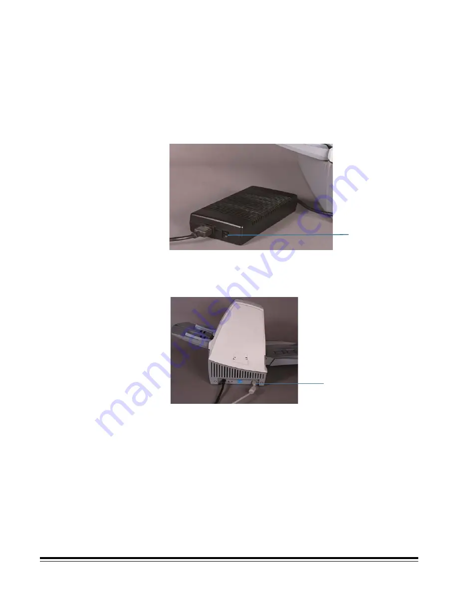
1. Press the side labeled “O” on the power switch to make sure that the 

power is off.

NOTE: The power switch is on the power supply.

2. Attach the power cord for your power type to the power supply.

3. Attach the power supply to the power input on the back of the scanner.

4. Plug the power cord into a power outlet.

NOTE: Make sure that the power outlet is located within 1.52 metres (5 feet) of 

the scanner and is easily accessible.

5. Press the side labeled “I” on the power switch to power up the scanner. 

After you power up the scanner, the red and green indicator lights will 
illuminate. After approximately one minute, both lights go out. When the 
green indicator light comes back on, the scanner is installed and ready to 
begin scanning. However, the host computer may require several seconds 
to detect the scanner.

For best calibration and scanning results, allow the scanner lamps to warm 
up for at least three minutes.

Power switch 

Beaded end of


IEEE 1394 cable

Summary of Contents for A-61514

Page 1: ...i100 Series Scanners User s Guide A 61514 Part No 9E3718 CAT No 126 4951...

Page 2: ...rmation 5 Acoustic emission 5 Power system 5 EMC statements 6 United States 6 Japan 6 Installing the scanner 7 Site specifications 7 System requirements 7 Minimum system configuration 7 Recommended sy...

Page 3: ...ce 21 Cleaning the scanner 21 Cleaning the separator module 22 Cleaning the feed module 23 Cleaning the drive rollers and transport area 24 Cleaning the imaging guides 25 Cleaning the paper path 26 Re...

Page 4: ...ng image quality and reliability Color at the same speed as bi tonal and grayscale Simultaneous color and bi tonal output Aggressive cropping capability to eliminate residual black border on any image...

Page 5: ...scale and color scanning NOTE Throughput speed at 400 dpi and 600 dpi is dependent upon your PC configuration Auto color balancing auto white balancing to ensure good color balance Pixel and color cor...

Page 6: ...ound in the most common business applications Optimal scanner performance is achieved when scanning documents within the recommended document specifications Scanning documents that are outside of thes...

Page 7: ...of any machinery These include but are not limited to the following Do not wear loose clothing unbuttoned sleeves etc Do not wear loose jewelry bracelets bulky rings long necklaces etc Hair should be...

Page 8: ...ontact Kodak locally for more information The product packaging is recyclable Parts are designed for reuse or recycling Acoustic emission Maschinenl rminformationverordnung 3 GSGV Der arbeitsplatzbezo...

Page 9: ...interference to radio or television reception which can be determined by turning the equipment off and on the user is encouraged to try to correct the interference by one or more of the following mea...

Page 10: ...ystem configuration To operate the scanner the following minimum configuration is required NOTE The actual performance of the system depends upon the scanning application choice of scanning parameters...

Page 11: ...k Capture Software Lite CD Read Me Now sheet User s Guide printed English version User s Guide pdf files in nine other languages are included on the Installation CD Registration sheet IEEE FireWire Ki...

Page 12: ...t of the box and place it on a stable level work surface that is capable of supporting it 2 Lift up the scanner door release to unlatch and open the scanner door 3 Remove the foam sheet 4 Lower the sc...

Page 13: ...EE 1394 FireWire port 4 Power input 5 Input tray 6 Input tray extender 7 Service LEDs 8 Upper imaging guide access door i160 Scanner only 7 1 2 4 5 6 3 8 Side 1 Red indicator 2 Green indicator See the...

Page 14: ...A 61514 September 2004 11 Internal 1 Separator module 2 Normal force rollers 3 Rear drive roller cover 4 Front drive roller cover 5 Feed module 1 2 3 4 5...

Page 15: ...94 FireWire card in your computer 2 Power up the host computer after the IEEE 1394 FireWire card installation is complete Installing the Kodak Driver Software 1 Insert the Kodak i100 Series Installati...

Page 16: ...power type to the power supply 3 Attach the power supply to the power input on the back of the scanner 4 Plug the power cord into a power outlet NOTE Make sure that the power outlet is located within...

Page 17: ...is running Windows 2000 the following screen may appear Select Yes Kodak has successfully tested the i100 Series Scanners with Windows 2000 Your scanner is now installed If you are installing the sca...

Page 18: ...04 15 1 Select Next The following screen appears 2 Select Continue Anyway Kodak has successfully tested the i100 Series Scanners with Windows XP The following screen appears 3 Select Finish Your scann...

Page 19: ...stall the tray Attaching the output tray 1 Locate the output tray slots on the scanner 2 Align the output tray pins with the slots 3 Press the output tray until it snaps into place Tray extenders and...

Page 20: ...est position with the second document stop raised when you are scanning documents that are 14 cm 5 5 in long 1 Grasp the tray on each side 2 Lift up the tray and move it up or down to the desired posi...

Page 21: ...ection For faster throughput feed documents into the automatic document feeder ADF in landscape orientation longer side as the leading edge IMPORTANT Staples and paper clips in documents may damage th...

Page 22: ...g with operator assistance When only a few documents from one batch remain in the feeder place the next batch face down on top of those documents Manual feeding Follow the guidelines for document size...

Page 23: ...eeder if they are placed in a protective plastic sleeve 1 Place the damaged document into a protective sleeve 2 Position the sleeve face down folded edge first and centered in the ADF 3 Lift the gap r...

Page 24: ...Refer to the MSDS for more information Allow all rollers to dry completely before using the scanner Use only non flammable cleans such as those provided through Kodak Parts Services Do not use cleaner...

Page 25: ...ents from the feeder area 3 Lift up the scanner door release to unlatch the scanner door 4 Pull up to open the scanner door 5 Remove the separator module by pulling it down and lifting it off 6 Manual...

Page 26: ...rator module clicks into place 10 Go to the next section to clean the feed module Cleaning the feed module 1 Push against the raised edge on the left side of the front drive roller cover to the side a...

Page 27: ...tray area under the feed module and the front roller cover 6 Insert the feed module by aligning the pins and pushing it toward the right to fit it into position 7 Re install the front drive roller co...

Page 28: ...ides Cleaning the imaging guides Clean the exposed top side surfaces of the imaging guides You do not need to remove the imaging guides for cleaning unless there is dust or dirt on the underside of th...

Page 29: ...Module for i100 Series Scanners 500 000 document pages Kodak Image Guides for i100 Series Scanners replace when guides are scratched or damaged NOTES The composition of the roller materials was engin...

Page 30: ...n your scanner in order to achieve the best overall quality of scanned images Frequent calibration is not needed or recommended Calibration instructions can be found in the Image Processing Guide for...

Page 31: ...you power up the scanner the red and green indicator lights will illuminate After approximately one minute both lights go out When the green indicator light comes back on the scanner is ready to begin...

Page 32: ...are lighter or heavier than normal Two additional positions for the separator module spring allow you to adjust the tension to improve the scanning of these types of documents The spring can be place...

Page 33: ...ow ready to use Color image quality Color image quality is highly subjective Here are some things to consider when scanning in color The difference in the color outputs of scanners printers and monito...

Page 34: ...signs of wear and replace these parts if necessary You can also power the scanner down and power up again or follow the instructions in System Is Not Responding in this section Calibration has failed...

Page 35: ...re being fed perpendicular to the feed module documents are being fed in the center of the ADF all staples and paper clips have been removed from the documents the feed module separator module and dri...

Page 36: ...supplier 1 Power down the computer 2 Power down the scanner 3 Disconnect the power cord from the back of the scanner 4 Disconnect the IEEE 1394 FireWire cable from the IEEE 1394 port on the back of th...

Page 37: ...th 8 9 to 43 2 cm 3 5 to 17 in Input Tray Capacity 150 sheets of 60 g 16 lb bond paper Recommended Daily Volume i150 i160 Scanner up to 1 000 pages day Light Source Xenon lamp Electrical Requirements...

Page 38: ...95 F Humidity 15 to 76 dry bulb Power Consumption i150 i160 9 5W Heat Load 600 BTU Altitude Up to 2440 m 8000 ft Acoustic Noise Data was measured in accordance with DIN 45 635 ANSI S12 10 1985 and ISO...

Page 39: ...roller tires 124 1066 Kodak Extra Large Feeder Consumables Kit for i100 Series Scanners 5 complete feed modules 5 complete separator modules 10 pre separation pads 120 roller tires 821 5808 Kodak Imag...

Page 40: ...Eastman Kodak Company 2004 CAT No 126 4951 EASTMAN KODAK COMPANY Document Imaging Rochester New York 14650 Kodak and Ektamate are trademarks of Eastman Kodak Company Printed on recycled paper DOCUMENT...

Reviews: