


7
3.
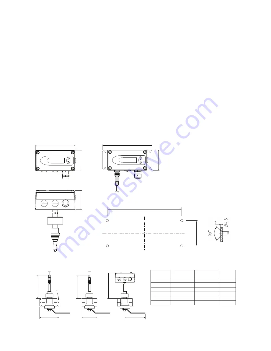
INSTALLATION
3.1. Mounting dimensions
3.1.1. KMT-1, KMT-2 and KMT-3
115
145
129
60
56
60
40
cable gland
M16x1.5
cable gland
M16x1.5
Cross-section
bore hole:
Drilling Plan:
The bottom part of the housing is mounted with
4 screws (not in the scope of supply)
Max. screw diameter: 4.5 mm (0.17 inch).
e.g. 4.2 x 38 mm DIN 7938H Screws
Measurement ball valve
Non-return protection for secure mounting
The patented non-return protection combines three functions in one device:
• Non-return protection
The sensor can only be pushed in one direction during installation. The sensor cannot return at all,
even if it is released.
• Seal
By means of an encapsulated O-ring, no compressed air can escape under pressure during assem-
bly.
• Precise positioning
The precise positioning with respect to immersion depth and orientation is easy to perform, guaran-
teeing accurate measurement results.
Mounting grip
With the mounting grip, the sensing probe is inserted and correctly positioned into the pipe line.
7
6
183
(7.2)
173
(6.81)
A
A
B
Only at DN15:
Reduction
3/4“-1/2“
173
(6.81)
Measurment
ball valve
Thread
A
B
DN15
R
p
1/2"
100±8
(3.94±0.32)
92
(3.62)
DN20
R
p
or NPT 3/4”
72
(2.83)
92
(3.62)
DN25
R
p
or NPT 1”
83
(3.27)
124
(4.88)
DN32
R
p
1 1/4"
100
(3.94)
124
(4.88)
DN40
R
p
or NPT 1 1/2"
110
(4.33)
147
(5.79)
DN50
R
p
or NPT 2”
131
(5.16)
147
(5.79)
dimensions in mm (inch)
Female thread: BSP thread acc. EN 10226 (old DIN 2999) or NPT
Summary of Contents for KMT-1
Page 36: ...www kobold com...