


USER MANUAL CENTRAL HEATING BOILER TYPE C38GC25; C38GC25-P; C38GC29; C38GC35; C38GC35-CH1; C38GC35-CH2
REV. 01.07.2019
23 din 37
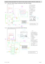
6.3.4
Graphic context – station startup control panel LMC1112
When started, the station is in an intermediary state for 5 seconds, necessary to initialise the system.
During this interval the diplay shows only the message “
On
” on the S1 symbol on the interface (see
figure 1.14).
6.3.5
Graphic context - Stand-by control panel LMC1112
This context is associated with an inactive/ waiting state of the central heating station. In the stand-by
state all the activation elements are inactive and every burning demand is ignored.
An exception to the rule:
the anti-freezing function
(generated by a value of water temperature in
the installation lower than 9°C, which will initiate a burning cycle to prevent the freezing of the thermal
agent in the installation.
Entering and exiting this regine is done by pressing
POWER
key for at least one second.
Possible actions:
-
POWER
– comute between ON/OFF states;
-
LIGHT
– activation or deactivation of light functions.
Figure 1.15 is an example of display in the stand-by state (pressure on the thermal circuit 1,8 bar).
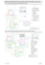
6.3.6
Graphic context – error state control panel LMC1112
The display of an error is sometimes asociated with a state of malfunctioning/ error of the station.
There are three types of errors:
-
Critical errors: all the activating/state elements of the central heating station are inactive and any
burning request is ignored. Getting out of this critical error state is done by pressing the RESET key;
-
Normal errors: all the activating/state elements of the central heating station are active and any
burning request is ignored. Getting out of a normal error state is done by pressing the RESET key;
-
Informative errors: all the activating/state elements of the central heating station are active and all burning requests are
accepted. Getting out of an informative state is done automatically when the cause of error disappears.
In this context the diplay flashes a message with the error code.
Possible actions:
-
RESET
– reset critical or normal errors;
-
LIGHT
- activation or deactivation of light functions – possible only if the central heating station is not in a state of critical
error.
Figura 1.16 is an example of display of an error (in our case E20).
6.3.7
Graphic context – waiting state control panel LMC1112
Waiting state is associated with a functioning state of the station, but with no burning request. All the
activating/state elements of the central heating station are active and all burning requests are accepted
if no error is present. In this state, the display shows pressure and thermal temperature, as well as the
functioning mode summer/ winter..
Possible actions:
-
POWER
- comute between ON/OFF states;
-
IN/SU
– comute between summer/ winter functioning modes;
-
LIGHT
- activation or deactivation of light functions;
-
CH+
- display and setting of maximum thermal temperature;
-
CH-
- display and setting of minimum thermal temperature;
-
DHW+
- display and setting of maximum hot water temperature;
-
DHW-
- display and setting of minimum hot water temperature.
Figura 1.17 is an example of display in the waiting state (pressure in the heating installation is 1,4 bar, working mode is
summer, and the temperature in the installation is 17°C
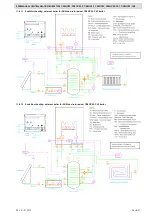
6.3.8
Graphic context – functioning state control panel LMC1112
This state is associated with the presence of flame or the functioning of the circulation pump of the station. In this state, all the
activating/state elements of the central heating station are active and the burning request is accepted. The display shows the
delivered instant temperature on the circuit meeting the request (heating ot hot water – symbols S5 or S6), regardless of the
presence or lack of flame, the pressure inside the installation and the functioning mode summer/ winter
Actiuni posibile:
-
POWER
- comute between ON/OFF states;
-
IN/SU
comute between summer/ winter functioning modes;
-
LIGHT
- activation or deactivation of light functions;
-
CH+
- display and setting of maximum thermal temperature;
-
CH-
- display and setting of minimum thermal temperature;
-
DHW+
- display and setting of maximum hot water temperature;
-
DHW-
- display and setting of minimum hot water temperature.
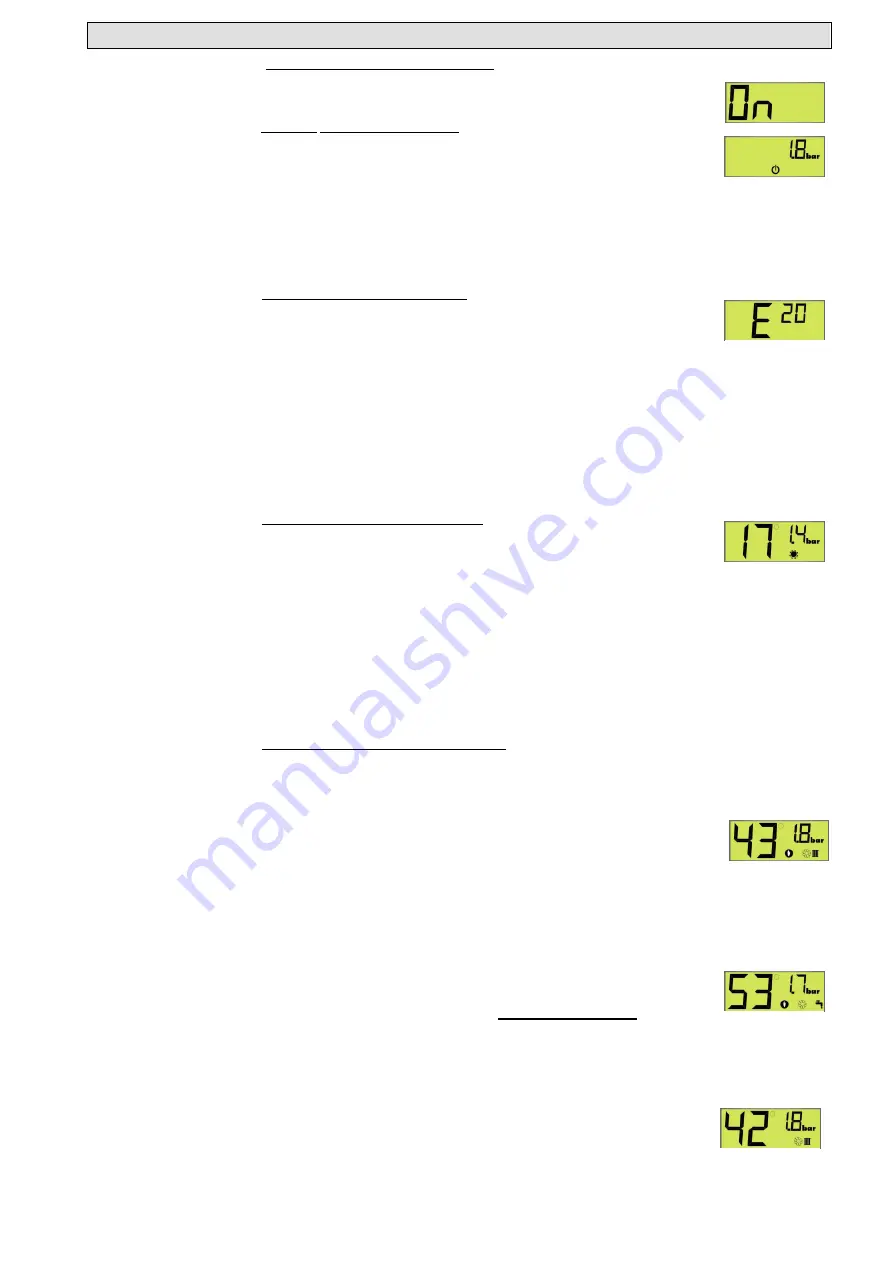
Figures 1.18 and 1.19 are two examples of graphic display of this context. Figure 1.18 – pressure in the heating installation is
1,8 bar, central heating station is in winter mode, flame is present, heating demand is satisfied and the instant thermal
temperature is 43°C;
Figura 1.19 – pressure in the heating installation is 1,7 bar, central heating station is set on winter
mode, flame is present, station deliveres hot water, and the instant hot water temperature is 53°C.
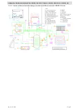
6.3.9
Graphic context – adjustment of functioning parameters control panel LMC1112
The adjustment of the main functions of the station (thermal temperature, hot water temperature) can be
done both in the waiting state and in the functioning state.
When we enter the state display of these values, the last value previously set will be displayed. Only in the period the set value is
displayed we can make changes of its value. Practically, at any moment of functioning of the station, by pressing
J1
(
CH+
) or
J2
(
CH-
) keys, the set value of the thermal temperature will be displayed and can be changed.
Similarlry, at any moment of functioning of the station, by pressing the
J3
(
DHW+
) or
J4
(
DHW-
) keys, the set value of the hot
water temperature will be displayed and can be changed.
While doing these settings, the display will show the value of the set temperature (thermal or hot water),
the pressure in the installation and the functioning mode of the station (winter/ summer).
Getting out of this setting mode
is done automatically if no key is pressed for at least 3 seconds
.
Fig.1.14
Fig.1.15
Fig.1.16
Fig.1.17
Fig.1.18
Fig.1.19
Fig.1.20


