


WORK TABLE SWING 360
°
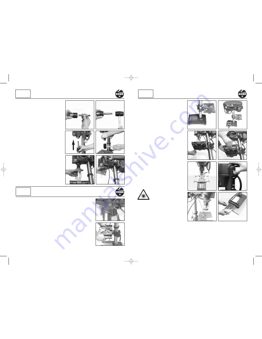
The work table can swing through 18O
°
to the
rear of the Pillar Drill in each direction – 36O
°
.
This will allow larger work pieces to be
accommodated on the base (Fig.23). Simply
unclamp the table (Fig.11) and rotate the table
either clockwise or anti-clockwise to the rear of
the Pillar Drill (Fig.22).
ADJUSTING THE TABLE WIDTH
Locate and loosen the wing nuts under the table
(Fig.24) and pull the side plates away from the
main table (Fig.25). This will allow support for
larger machine vices and pieces of work (Fig.26)
Once the side plates are in place don’t forget to
re-tighten the wing nuts.
LASER GUIDE
Located under the drilling head stock is a laser
guide which is switched on using the on/off
switch located on the front of the drilling head
stock above the depth stops (Fig.27). It provides
target cross-hairs (Fig.28) which once set on
your first workpiece of a batch will facilitate the
accurate placement of subsequent pieces.
This Class 2 laser can potentially
cause severe damage to eyes.
Never look directly into the laser
beam or point the laser beam at
people either directly or indirectly through
reflective surfaces.
INTEGRAL DRILL STORAGE TRAY
Conveniently located in the base of the drill is a
handy storage tray for keeping your drill bits
organised and close at hand. (Fig.29).
QUILL SPRING ADJUSTMENT
WARNING: The quill spring is under extreme tension.
The quill spring is located in a chrome housing on the opposite side of the feed shaft boss and returns the
spindle to its uppermost position. Adjustment is normally only required after many hours of use when it
fails to return the spindle to its uppermost position. With the spindle in its uppermost position it can be
ADJUSTING THE TABLE HEIGHT
(Fig.10 & 11)
To adjust the table height, slacken the clamping lever at the rear of the table
support assembly (Fig. 11).
Using the winding handle, raise table up or down to desired height (Fig. 10).
When the desired height has been achieved, do not forget to re-secure the
clamping lever.
TILTING THE TABLE ± 45
°
With a suitable spanner/wrench loosen the securing bolt underneath the table
(Fig.20). On the table support assembly casting there is a graduated 0 - 45
°
scale (Fig.21). Set the table to the required angle and re-tighten the bolt.
NOTE:
The graduated scale is for guidance only. We recommend the use of an
engineers protractor when setting any angles.
8
9
Make sure you locate the tang on the adaptor
with the slot in the drive spindle. To make
doubly sure, place a piece of wood on the table
and wind the manual feed handle to bring the
chuck down onto the wood pressing the chuck
tighter onto the spindle adaptor.
To remove or replace the chuck, tap the side of
the chuck in a downward motion with a soft
mallet (Fig.35 on page 11).
FITTING THE TELESCOPIC GUARD
Position the clear plastic shield into the red
collar and secure in place with the two small
cross head screws. Place over the chuck and
locate onto the drill head collar (Fig.18). Tighten
the cross-head clamping screw (Fig.19) but
don’t over tighten as this may break the plastic
body. Check that the guard lifts easily and stays
lifted to change drills/cutting tools.
Fig.14
KOBE
I N D U S T R I A L
POWER TOOLS
ASSEMBLY
continued
Fig.15
Fig.16
Fig.17
Fig.19
Fig.18
Fig.25
Fig.24
Fig.26
Fig.28
KOBE
I N D U S T R I A L
POWER TOOLS
SETTING UP & ADJUSTMENT
KOBE
I N D U S T R I A L
POWER TOOLS
SETTING UP & ADJUSTMENT
Fig.23
Fig.22
Fig.20
Fig.21
Fig.27
Fig.29
KBE-271-2110K_Instructions.qxd 09/06/2009 09:34 Page 8


