background image


TEMON 4-C 

Doc. N°

 MO-0368-ING 


Microener. - Copyright 2010  


2.1 

Date 

01.12.2008


Rev. 


Pag. 

10


of 

14


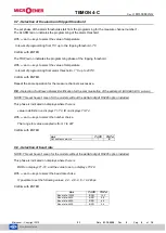
9.10 - Selection data bit, parity and stop bit 


NOTE: This 

set haven’t mean for the models without the 

serial output

 RS485 option installed. 

 
This phase is indicated on displays where there is 


The type of parity on displays T1-T2 ; number of data bit and stop bit on display T3-T4. 

 
With 

 and 

 keys to select the set choice. 

 
Confirm with ENTER. 


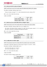
9.11 - Selection of the channel linked to the analogical output 


NOTE: This set haven’t mean for the models without the analogical output option installed. 

 
This phase is indicated on displays where there is an on displays T1-T2, 


the measure of the linked channel on displays T3-T4 (CH 1/2/3/4 for measure channel 1 / 2 / 3 / 4, all to link 
the output on the measure channel with the highest temperature). 

 
With 

 and 

 keys to select the set choice. 

 
Confirm with ENTER. 


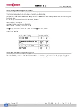
9.12 - Configuration of output signal 


NOTE: This set haven’t mean for the models without the analogical output option installed. 

 
In this phase it’s possible to program one of the two type of signal: 0 ÷ 20 mA or 4 ÷ 20 mA. 
 
This phase is indicated on displays where there is 


an0 -20 to set the output as 0 ÷ 20 mA or 
an4 -20 to set the output as 4 ÷ 20 mA. 

 
With 

 and 

 keys to select the options. 

 
Confirm with ENTER. 
 
The maximum load for analogue output is 400


Set 

T1-T2 

T3-T4 

No parity / 8 data bit 

– 1stop bit 

NO 

8-1 

No parity / 8 data bit 

– 2stop bit 

NO 

8-2 

Even parity / 8 data bit 

– 1stop bit 

EVE 

8-1 

Odd parity / 8 data bit 

– 1stop bit 

ODD 

8-1 

Linked channel 

T1-T2 

T3-T4 

Channel with the highest temperature 

AN 

all 

Measure channel CH 1 

AN 

ch1 

Measure channel CH 2 

AN 

ch2 

Measure channel CH 3 

AN 

ch3 

Measure channel CH 4 

AN 

ch4 

Signal configuration 

T1-T2 

T3-T4 

Output proportionally 0 

– 20 mA 

AN 0 

-20 

Output proportionally 4 

– 20 mA 

AN 4 

-20 

Summary of Contents for MICROENER TEMON 4-C

Page 1: ...TEMON 4 C Doc N MO 0368 ING Microener Copyright 2010 FW 2 1 Date 01 12 2008 Rev 0 TEMPERATURE MONITOR DEVICE TYPE TEMON 4 C OPERATION MANUAL...

Page 2: ...entification for the communication of the serial port MODBUS RTU protocol ____________________ 9 9 9 Selection of baud rate ____________________________________________________________________________...

Page 3: ...are available two levels of alarm alarm tripped that active the commutation of the relative output relay for signalling at distance or to disable the machine under control On front of the instrument...

Page 4: ...noises it s necessary to use the following indication for the wires of measure of the Pt100 to use probes with shielded wire connected at earth and wires twisted to separate the wires of the probes fr...

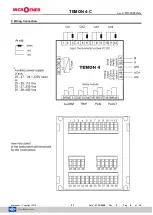
Page 5: ...TEMON 4 C Doc N MO 0368 ING Microener Copyright 2010 2 1 Date 01 12 2008 Rev 0 Pag 5 of 14 7 Wiring Connection...

Page 6: ...annels 5 LED FAULT of indication failure device or thermometric probes 6 LED HOLD of indication function of manual reset activated 7 LED FAN of indication activation output of ventilation 8 push butto...

Page 7: ...in the menu programming SET in this phase of programming the HOLD led switch on The Hold function allows to store the alarm condition that can be rearmed only manually with the RESET button when the...

Page 8: ...it s necessary to select the modality of functioning ventilation 9 5 Selection threshold of disable ventilation The FAN led on with fixed light indicates this phase of programming With and keys to se...

Page 9: ...ion of address network identification for the communication of the serial port MODBUS RTU protocol NOTE This set haven t mean for the models without the serial output RS485 option installed This phase...

Page 10: ...the highest temperature With and keys to select the set choice Confirm with ENTER 9 12 Configuration of output signal NOTE This set haven t mean for the models without the analogical output option in...

Page 11: ...n temperature FDC min 5 C max 30 C and after the time in which to do the control FDC min 10 max 90 period in seconds The key is used to increase the values while the key to decrease Confirm with ENTER...

Page 12: ...old value set the flashing optical signalling will be automatically deleted 11 Diagnostic The device is provided of the thermic probes diagnostic function The condition controlled on the measure input...

Page 13: ...inputs 1 and 2 On the right display on the front panel will appear the temperature of the measure channel hotter between the inputs 3 and 4 To come back in the standard modality of measure visualizat...

Page 14: ...m depth 120mm Enclosure thermoplastic self extinguishing as UL94 V0 working temperature 10 55 C humidity max 90 storing temperature 25 80 C standards electromagnetic compatibility CEI EN 50081 2 CEI E...

Reviews: