background image


TEMON 4-C 

Doc. N°

 MO-0368-ING 


Microener. - Copyright 2010  


2.1 

Date 

01.12.2008


Rev. 


Pag. 

14


of 

14


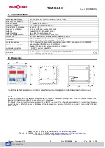
17. Technical Features 


auxiliary power supply 

20÷250Vca/cc   ±15%  or 115-230-400 Vca 50-60Hz


maximum consumption


4 VA 

measure inputs


3 - 4 inputs by RTD Pt100 

interval of measure 

0 °C ÷ +220 °C / precision ±  2 °C 

tripped delay - hysteresis 

5 seconds 

– 2 °C


measure visualization 

2 displays with led 7 segments, 3 digit


outputs 

4 relay NO-C-NC, 8 A resistive load


output functions 

alarm, trip, fan, auto-diagnostic 

functions programmable 

ALARM, TRIP, HOLD, FAN, T.MAX, HOT 

connection 

extractible terminal with screws, section wires max 2,5 mm

2


insulation 

2500 Vrms 50 hz per 60 sec :U aux - input Pt100 /  
U aux - relay outputs / inputs Pt100 - relay outputs 

protection degree 

IP52 front panel (IP65 with optional protection cover), IP20 rear panel, as CEI-EN 60529 

dimensions 

– enclosure 

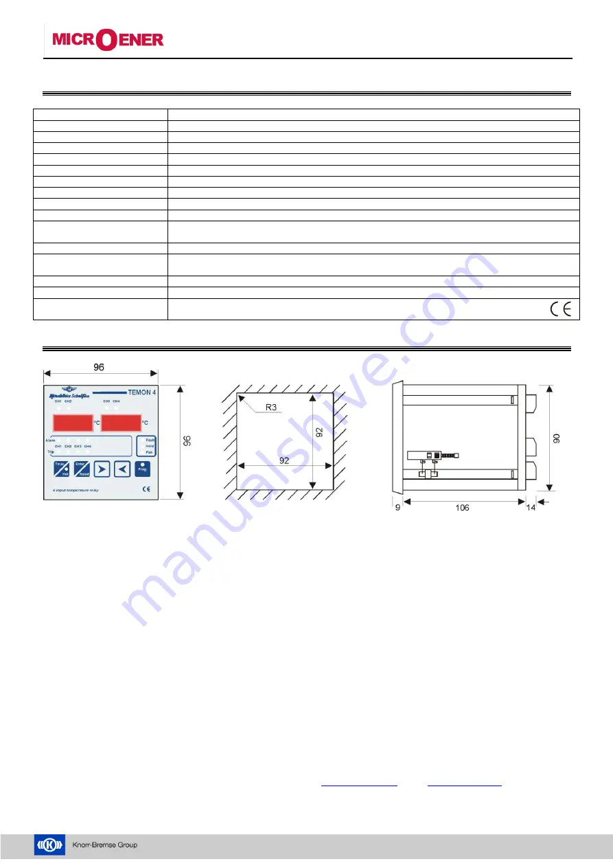
flash mounting DIN 96x96mm, depth 120mm /  
Enclosure thermoplastic self-extinguishing as UL94 V0 

working temperature


-10 ÷ 55°C, humidity max 90% 

storing temperature


-25 ÷ +80°C 

standards


electromagnetic compatibility CEI-EN 50081-2 CEI-EN50082-2 
security CEI 41.1, CEI-EN 60255- 


18. Dimensions 


Contact t

he technical assistance or refer at specific document for application don’t described in this manual. 


NOTE 
At reason of the evolution of standards and products, the company reserves to modify in every time  the features of the product 
described in this d

ocument, that it’s necessary to verify preventively. 

The liability of the producer for damage caused by defect of the product ”can be reduced or deleted (…) when the damage is 
caused joint by a defect of product or for blame of the damaged or a person of w

hich the damaged is responsible” (Article 8, 

85/374/CEE).


Quartier du Pavé Neuf,49 rue de l’Université – 93160 Noisy le Grand - France


Tél : +33 1 48 15 09 09 

– Fax : +33 1 43 05 08 24 email 

[email protected]

 - http:/

www.microener.com


Les cotes, schémas et spécifications n’engagent Microener qu’après confirmation 


Summary of Contents for MICROENER TEMON 4-C

Page 1: ...TEMON 4 C Doc N MO 0368 ING Microener Copyright 2010 FW 2 1 Date 01 12 2008 Rev 0 TEMPERATURE MONITOR DEVICE TYPE TEMON 4 C OPERATION MANUAL...

Page 2: ...entification for the communication of the serial port MODBUS RTU protocol ____________________ 9 9 9 Selection of baud rate ____________________________________________________________________________...

Page 3: ...are available two levels of alarm alarm tripped that active the commutation of the relative output relay for signalling at distance or to disable the machine under control On front of the instrument...

Page 4: ...noises it s necessary to use the following indication for the wires of measure of the Pt100 to use probes with shielded wire connected at earth and wires twisted to separate the wires of the probes fr...

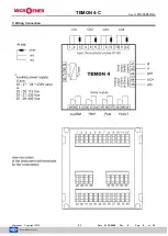
Page 5: ...TEMON 4 C Doc N MO 0368 ING Microener Copyright 2010 2 1 Date 01 12 2008 Rev 0 Pag 5 of 14 7 Wiring Connection...

Page 6: ...annels 5 LED FAULT of indication failure device or thermometric probes 6 LED HOLD of indication function of manual reset activated 7 LED FAN of indication activation output of ventilation 8 push butto...

Page 7: ...in the menu programming SET in this phase of programming the HOLD led switch on The Hold function allows to store the alarm condition that can be rearmed only manually with the RESET button when the...

Page 8: ...it s necessary to select the modality of functioning ventilation 9 5 Selection threshold of disable ventilation The FAN led on with fixed light indicates this phase of programming With and keys to se...

Page 9: ...ion of address network identification for the communication of the serial port MODBUS RTU protocol NOTE This set haven t mean for the models without the serial output RS485 option installed This phase...

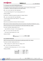
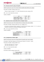
Page 10: ...the highest temperature With and keys to select the set choice Confirm with ENTER 9 12 Configuration of output signal NOTE This set haven t mean for the models without the analogical output option in...

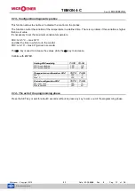
Page 11: ...n temperature FDC min 5 C max 30 C and after the time in which to do the control FDC min 10 max 90 period in seconds The key is used to increase the values while the key to decrease Confirm with ENTER...

Page 12: ...old value set the flashing optical signalling will be automatically deleted 11 Diagnostic The device is provided of the thermic probes diagnostic function The condition controlled on the measure input...

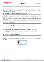
Page 13: ...inputs 1 and 2 On the right display on the front panel will appear the temperature of the measure channel hotter between the inputs 3 and 4 To come back in the standard modality of measure visualizat...

Page 14: ...m depth 120mm Enclosure thermoplastic self extinguishing as UL94 V0 working temperature 10 55 C humidity max 90 storing temperature 25 80 C standards electromagnetic compatibility CEI EN 50081 2 CEI E...

Reviews: