background image

Servicing

Diaphragm pump N87.9 EX

32

Translation of Original Operation and Installation Instruction, english, KNF 323252 04/21

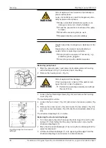
Fig.8 Replacing the structured di-
aphragm

4. Loosen the four screws ( Fig. 8/5).

5. Remove the head plate ( Fig. 8/4) and the intermediate plate ( Fig.

8/1).

The structured diaphragm (8) is visible.

Replacing the structured diaphragm

1. Turn the pump to the side; this keeps the shim rings (10) and the disk

springs (11) from falling into the pump chamber when removing the
structured diaphragm (8).

2. Move the structured diaphragm (8) by turning the counterweight to top

dead center.

3. Lift the structured diaphragm (8) onto opposing side edges; hold the

structured diaphragm and unscrew it counterclockwise.

4. Remove the diaphragm support (9), shim ring(s) (10) and disk spring

(11) from the threaded bolt of the structured diaphragm (8) and keep in
a safe place.

5. Check all parts for contamination and clean them if necessary.

6. Push the diaphragm support (9), shim ring(s) (10) and disk spring (11)

onto the threaded bolt of the new structured diaphragm (8) in this order
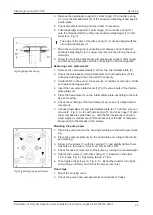
(see  Fig. 9).

Fig.9 Aligning disk spring

The edge of the disc of the disc spring (11) must be aligned with the
structured diaphragm (8).

7. Move the connecting rod (connection part between drive shaft and

structured diaphragm) to top dead center by turning the counterweight.

8. Screw the structured diaphragm with diaphragm support, shim ring(s)

and disk spring clockwise onto the connecting rod and hand tighten.

Replacing the valve plates/seals

1. Separate the head plate (4) from the intermediate plate (1).

2. Remove the valve plates/seals (2) from the intermediate plate (1).

3. Check the valve seats, intermediate plate (1) and head plate (4) for

contamination and damage. Clean the parts if necessary.

4. Contact KNF in the event of unevenness, scratches or corrosion. Order

and replace damaged parts.

The valve plates/seals are identical for the pressure and suction
side. The same applies for the top and bottom of the valve plates/
seals.

5. Insert the new valve plates/seals (2) in the valve seats of the intermedi-

ate plates (1).

6. Place the head plate (4) on the intermediate plate according to the felt-

tip pen marking.

7. Check the centering of the head plate (4) by means of a slight lateral

movement.

Summary of Contents for N 87 TTE

Page 1: ...RIGINAL OPERATION AND INSTALLATION INSTRUCTION ENGLISH KNF 323252 04 21 ATEX Notice Before operating the pump and the accessories read the operating and installation instructions and observe the safet...

Page 2: ...function 15 6 Transport 17 7 Installation and connection 18 8 Operation 22 9 Servicing 25 10 Troubleshooting 34 11 Spare parts and accessories 37 12 Returns 38 13 Appendix 39 KNF Neuberger GmbH Alter...

Page 3: ...ep the operating and installation instructions within reach at all times Project pumps For customer specific project pumps pump models that begin with PJ or PM there may be deviations from the operati...

Page 4: ...danger level Measures for avoiding the danger and its consequences are specified here Danger levels Signal word Meaning Consequences if not observed DANGER warns of immediate danger Death or serious i...

Page 5: ...entially numbered steps This symbol indicates important information Explanations of pictograms Pictogram Meaning General warning symbol Warning of hot surface Warning of electrical voltage Warning of...

Page 6: ...risk of releasing dangerous gases and vapors from the pump system Requirements on the transferred medium Before transferring a medium check whether the medium can be trans ferred danger free in the s...

Page 7: ...roups T4 Temperature class see Chapter 2 4 4 Temperature classes Gb Equipment protection level See Chapter 2 4 6 Equipment protection level for gas Special operating conditions See Chapter 2 4 7 Speci...

Page 8: ...isting of gases vapors or mists forms occasionally 2 2G Devices that extract from zone 1 and are designed for use in areas in which it is to be expected that an explosive atmos phere consisting of gas...

Page 9: ...fuel Jet fuel Heating oils n hexane Acetalde hyde IIB Town gas Ethylene Ethyl alcohol Hydrogen sulfide Ethyl ether IIC Hydrogen Acetylene Carbon disulfide Tab 5 The classification of gases and vapors...

Page 10: ...r mixture in which it is used Temperature class The maximum surface temperature arises from the design of the pump and is specified as temperature class Temperature class Max surface temperature C Ign...

Page 11: ...ith high protection level for use in potentially explosive areas in which there is no risk of ignition during normal operation or in the event of fore seeable or infrequent faults malfunc tions High G...

Page 12: ...r supply and de energized Ensure that no hazards arise from gas flowing when gas connections are open from the effects of noise or from hot corrosive dangerous and envi ronmentally hazardous gases Cla...

Page 13: ...e operating pressure of the pump The maximum permissible operating pressure of the pump is stated in Chapter 4 Technical data Make certain that the permissible ambient temperature 4 Technical data is...

Page 14: ...1013 mbar Other parameters Parameter Value Permissible ambient temperature C F 5 to 40 Permissible media temperature C F 5 to 40 Dimensions See Fig 3 Chapter 7 1 Installing the pump Electrical data Se...

Page 15: ...Translation of Original Operation and Installation Instruction english KNF 323252 04 21 15 5 Design and function Design 1 Pump outlet 2 Pump inlet 3 Pump head 4 Motor type plate 5 Motor 6 Type plate...

Page 16: ...2 Function of a diaphragm pump Diaphragm pumps transfer compress depending on the version and evacu ate gases and vapors The elastic diaphragm 4 is moved up and down by the eccentric 5 and the connec...

Page 17: ...e is a risk of injury from cutting on the sharp edges when grabbing corners or when opening the packaging Where appropriate wear suitable personal protective equipment e g safety shoes safety gloves T...

Page 18: ...tures during pump op eration Depending on the medium being transferred breakage of the media contacting components can result in a dangerous mixture if the medium mixes with the air in the compressor...

Page 19: ...Make sure that the installation location is dry and that the pump is pro tected from rain splash water gushing water dripping water and other contamination Make sure that the installation location is...

Page 20: ...t is recommended that an additional EMERGENCY STOP device be installed Potentially explosive atmospheres Only place the electrical equipment in potentially explosive atmos pheres that is necessary the...

Page 21: ...certain cir cumstances occur at the pneumatic outlet of the pump Decoupling KNF recommends mechanically decoupling the pump from the pipe system e g through the use of flexible hoses or pipes In this...

Page 22: ...WARNING Injury to eyes Coming too close to the inlet outlet of the pump may result in injury to the eyes due to the present vacuum operating pressure Do not look into the pump inlet outlet during ope...

Page 23: ...is not exceeded Ensure that the pump outlet is not closed or restricted WARNING Risk of explosion from elevated ambient tempera ture Monitor the ambient temperature compres sion heat motor heat Ensur...

Page 24: ...not be started up against pressure or vacuum dur ing switch on This also applies during operation after a brief power failure Ensure that normal atmospheric pressure is present in the lines when switc...

Page 25: ...ng schedule Have the motor bearing replaced by KNF ac cording to servicing schedule WARNING Risk of explosion if genuine spare parts are not used If original parts are not used the pump loses its expl...

Page 26: ...ing properties of the bearing grease etc It is the operator s responsibility to assess these factors 9 2 Cleaning 9 2 1 Flushing the pump WARNING Risk of explosion by flushing the pump with air In pot...

Page 27: ...pump and free the pump of hazardous materials Spare parts Spare part Item designation Number per pump head Structured diaphragm 7 in Fig 4 1 Valve plates seals 12 in Fig 4 2 Tab 15 According to spare...

Page 28: ...g 1 to ensure proper mounting 2 Remove the housing cover Fig 3 WARNING Risk of explosion from damage If the housing cover is bent or if the paint is dam aged there is no risk of explosion Perform the...

Page 29: ...rrosion Order and replace damaged parts 4 Insert the new valve plates seals 12 in the valve seats of the interme diate plates 6 5 Place the head plate 5 on the intermediate plate according to the felt...

Page 30: ...similar injuries Before recommissioning observe the applicable standards guide lines regulations and technical standards at the electrical connec tion 9 4 Changing the structured diaphragm and valve...

Page 31: ...o dangerous substances in the pump Depending on the medium being transferred caustic burns or poisoning is possible Wear protective equipment if necessary e g protective gloves goggles Clean the pump...

Page 32: ...new structured diaphragm 8 in this order see Fig 9 Fig 9 Aligning disk spring The edge of the disc of the disc spring 11 must be aligned with the structured diaphragm 8 7 Move the connecting rod conn...

Page 33: ...ghtening torque 2 1 Nm Final steps 1 Mount the housing cover 2 Check the pump head and pneumatic connections for leaks 3 Properly dispose of the replaced structured diaphragm and valve plates seals To...

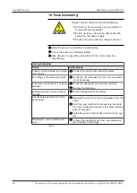
Page 34: ...ult remedy Pump is not connected to the elec trical mains Connect the pump to the electrical mains No voltage in the electrical mains Check the circuit breaker for the room and switch it on if necessa...

Page 35: ...tled Disconnect the pump from the system to deter mine the output values Eliminate any throttling e g valve if necessary Use lines or connection parts with a larger cross section if necessary Leaks oc...

Page 36: ...pump to KNF Customer Service contact data see www knf com 1 Flush the pump with air for a few minutes if necessary for safety rea sons with inert gas to free the pump head of dangerous or aggressive...

Page 37: ...rder spare parts and accessories please contact your KNF sales partner or KNF Customer Service contact data see www knf com 11 1 Spare parts Spare part Order number Valve plate seal 057172 Structured...

Page 38: ...the pump see Chapter Cleaning the pump 4 Send the pump together with the completed Health and Safety Clear ance and Decontamination Form to KNF stating the nature of the transferred medium 5 Pack the...

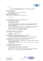
Page 39: ...87 9 EX Appendix Translation of Original Operation and Installation Instruction english KNF 323252 04 21 39 13 Appendix 13 1 Declaration of Conformity For further information see also Konformit tserkl...

Page 40: ......

Page 41: ......

Page 42: ......

Page 43: ......

Page 44: ...mp N87 9 EX 44 Translation of Original Operation and Installation Instruction english KNF 323252 04 21 13 2 Motor For further information see also Betriebsanleitung Motor pdf Anschlussplan Motor pdf C...

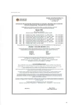
Page 45: ...cable entry supplied with the motor or through another type of cable entry certified in accordance with the European Standards showed above in compliance with Directive 2014 34 EU and IECEx approved...

Page 46: ...EN 60079 0 2012 A11 2013 EN 60079 1 2014 EN 60079 31 2014 EN 60079 7 2015 EN 60034 1 2 5 6 7 9 12 14 IEC60072 1 EN 60259 NOTA NOTE BEMERKUNG NOTAS Directive 2006 42 EC Direttiva Macchine Machinery Dir...

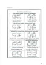
Page 47: ...ti separati Three phase double speed 2 separate windings U1 V1 W1 W2 U2 V2 L3 L1 L2 L1 L2 L3 U1 W2 U2 V2 W1 V1 U1 V1 W1 W2 U2 V2 L3 L1 L2 L1 L2 L3 U1 W2 U2 V2 W1 V1 1 T1 2 T2 1 T1 2 T2 Bassa velocit L...

Page 48: ......

Page 49: ...accessory Terminal box and Capacitor box Type of Protection Flameproof enclosures d Equipment dust ignition protection by enclosure t Increased safety e Marking Ex db IIC T3 T4 or T5 Gb Ex tb IIIC T1...

Page 50: ...variations to it specified in the schedule of this certificate and the identified documents was found to comply with the following standards IEC 60079 0 2011 Edition 6 0 Explosive atmospheres Part 0...

Page 51: ...IIC and IIIC All the parts of the flameproof enclosures have flameproof joints independent from each other The motors can be equipped with auxiliary devices heaters thermal protectors Possibility of s...

Page 52: ...08 DETAILS OF CERTIFICATE CHANGES for issues 1 and above Changing of manufacturer s references Use of metric threaded plugs in holes of flameproof terminal enclosure with a free internal volume up to...

Page 53: ......

Page 54: ......

Page 55: ......

Page 56: ...KNF worldwide You can find our local KNF partners at www knf com...

Reviews: