background image

P 2.1L user manual V6840, version 

3.

5

Installation

13

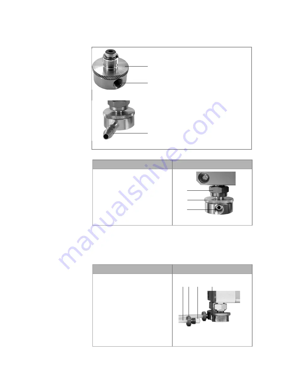
Eluent Inlet

The eluent lines are connected by the eluent inlet to the pump head. Before 
the eluent lines are connected, the eluent inlet must be attached to the 
pump head.

Connecting the Eluent Inlet to the Pump Head

Connecting the Eluent Line

Prerequisite

The eluent inlet has been connected.

Note: 

If connecting a pump head from 100 – 500 ml, make sure that the 

tapered side of the cutting ring is pointed towards the fastening screw of 
the Teflon tube.

Legend

1

Knurled-head screw

2

Eluent inlet

3

Olive-type tube fitting

Fig. 8

Eluent inlet for 100-500 ml pump heads

Fig. 9

Eluent inlet for 1000 ml pump head

1

2

3

Procedure

Process

Figure

1. With the knurled-head screw 

2

,

screw the eluent inlet into the
inlet screw fitting 

1

 of the

pump head.

2. Turn the eluent inlet until the

intake manifold input 

3

 points

forward.

3. Tighten the knurled-head screw.

Fig. 10

Eluent inlet, variant 1

1

2

3

Procedure

Process

Figure

Pump head:

100 ml

250 ml

500 ml

1. Push the Teflon hose 

1

 through

the fastening screw 

2

 and the

cutting ring 

3

.

2. Insert the hose end as far as pos-

sible into the eluent inlet fitting

4

 of the pump head.

3. Tighten the fastening screw by

hand.

Fig. 11

Connecting the eluent line to 
the pump head

2

1

3

4

Summary of Contents for Azura V6840

Page 1: ...Pump P 2 1L User Manual V6840...

Page 2: ...ing 11 Connecting the Piston Backflushing 12 Eluent Inlet 13 Connecting the Eluent Inlet to the Pump Head 13 Connecting the Eluent Line 13 Changing the Setup to LPG 14 Mounting the Valve Block 14 Conn...

Page 3: ...leaning and Caring for the Device 33 Pump Head 33 Screw Fittings on the Pump Head 34 Dismounting the Pump Head 34 Attaching Capillaries to the Pump Head 35 Check Valves 35 Removing the Check Valves 35...

Page 4: ...nt of the device could fail Device Overview P 2 1L is a self priming pump with automatic piston backflushing that is used in preparative HPLC systems Legend 1Status LEDs 2Pump head 3Pressure sensor Fi...

Page 5: ...redients API Features The pump transports the fluid By choosing the pump head accordingly it is possible to reach the following maximum values Pressure up to 400 bar at a 100 ml min flow rate Flow rat...

Page 6: ...at 4 C 25 C 39 2 F 77 0 F 1 Acetonitrile2 Benzene Dilute acetic acid e g 10 50 at 25 C 77 0 F Dilute ammonia solution Dilute sodium hydroxide 1 M Ethyl acetate Ethanol1 Hexane heptane at 4 25 C 39 2...

Page 7: ...to lab regulations and wear protective clothing Safety glasses with side protection Protective gloves Lab coat What must be taken into account All safety instructions in the user manual The environmen...

Page 8: ...ng off the power switch or by pulling the power plug Opening the Device The device may be opened by the KNAUER Technical Support or any com pany authorized by KNAUER only Signal Words Possible dangers...

Page 9: ...n the side of the housing only Lifiting Clasp the device at its side panels and lift it out of the packaging Do not hold onto front cover or leak tray Location Requirements The location for the device...

Page 10: ...at orders Tool Utility knife Bruising danger Damage to the device by carrying or lifting it on protruding housing parts The device may fall and thus cause injuries Lift the device on the side of the h...

Page 11: ...e flush pump are located on the front of the device Flushing solution These are suitable flushing solutions Water Mixture of 80 water and 20 ethanol Isopropanol Device defect Damage to the pump head c...

Page 12: ...ew 2Eluent inlet 3Olive type tube fitting Fig 8 Eluent inlet for 100 500 ml pump heads Fig 9 Eluent inlet for 1000 ml pump head 1 2 3 Procedure Process Figure 1 With the knurled head screw 2 screw the...

Page 13: ...block for flow rates in the range of 100 800 ml min You can not use the front cover after having mounted the valve block Mounting the Valve Block Prerequisite The pump has been switched off The power...

Page 14: ...f the valve block 2 with a 7 5 Nm torque Fig 15 Valve block 4 Insert the plug into the female connector 4 Fig 16 Socket for the LPG valve block Procedure Process Figure 2 3 4 Procedure Process Figure...

Page 15: ...tered by the leak sensor the LED flashes red Both the device and the data acquisition via chromatogra phy software are stopped Prerequisite The front cover has been removed Procedure Process Figure 1...

Page 16: ...and error signals to external devices 3 Connect the nozzle and the fun nel 4 Push the other end of the hose onto the nozzle 5 of the leak tray Fig 22 Hose connected to device 5 For the bottom device p...

Page 17: ...g output signal Either outputs the measured sys tem pressure or a control voltage for Pump B The out put range can be set to values of max 1 2 5 and 10 V ANALOG IN Analog input signal for controlling...

Page 18: ...assive 0 V active 5 V Pulse 5 V for at least 1000 ms 2TTL TTL compatible output Levels passive 0 V active 5 V Pulse 5 V for at least 1000 ms 3OC TTL output Levels passive 0 V active 5 V Pulse 5 V for...

Page 19: ...oftware Steady rate signal passive open relay contact active closed relay contact Pulse Closed relay contact for at least 1000 ms Permissible load of the relay contact 1 A 24 V DC Analog GND Reference...

Page 20: ...trip 3 on a suitable sur face 2 Push the depressor tool 1 into the opening on the upper side 3 Continue pushing the depressor tool down and lead the cable 2 into the front end of the terminal strip 4...

Page 21: ...e Configuring the LAN Settings The LAN uses only one server which is normally the router from that the devices automatically receive their IP address Prerequisite In Windows power saving hibernation s...

Page 22: ...and password are printed These information help to open the router configuration Process 1 To open the router configuration start your Internet browser and enter the IP address not for all routers 2 E...

Page 23: ...e we recommend to set a static IP address for certain applications Prerequisites The device has been switched on Mobile Control has been installed and started The connection between the Mobile Control...

Page 24: ...id through the dry feed hoses up to the pump head with the provided syringe If you are working without the pump head inlet pay attention that both feed hoses are filled with solvent Column defect Dama...

Page 25: ...her and ClarityChrom version 3 0 7 or higher You will find a detailed description on the chromatography software in the software manual Control Unit To control the device with the external Control Uni...

Page 26: ...rized by KNAUER performs this functionality test during the installation The Installation Qualification is a standardized document that comes as part of the delivery and includes the following confirm...

Page 27: ...ed Connection not established If no connection was established test the following Is the router switched on Is the patch cable connected correctly to the router and the com puter 2 Check the router se...

Page 28: ...ump head to remove the air bub bles Let the pump run for 1 h Always tighten the inlet screw 1 and outlet screw 1 on the pump head with a torque wrench and 15 Nm Clean the ball valves Exchange the ball...

Page 29: ...echnical Support of the manufac turer in case the system message repeats itself C Cannot edit pro gram from the run ning link First stop the link and then edit the data on the device display or with t...

Page 30: ...valid line number Change the entry in the program line Invalid time in time table Correct the time entry L Leak sensor not pres ent Switch the device off and then on If the leak sensor is still not pr...

Page 31: ...is running Quit program or wait until program has been completed Program not com patible with pump head Modify the program or replace the pump head S Sum of components is not 100 Change the entry T Th...

Page 32: ...any technical questions regarding the hardware or software of the manufacturer please use one of the contact options below Technical Support hotline European hotline Languages Available by telephone...

Page 33: ...h at a time Intermediate result The pump head is dismounted To mount the pump head proceed the steps in reverse order Legend 1Capillary fitting 2Allen screws 3Outlet fittings 4Inlet fittings 5Eluent I...

Page 34: ...alves do not open and close properly They cause pressure fluc tuations and irregular flow If it is impossible to clean the check valves replace the whole unit Removing the Check Valves Prerequisite Th...

Page 35: ...Device defect Damage to the pump head caused by overtightened capillary fittings Note the torque of the fittings Use 5 Nm torque for stainless steel fittings Use 1 Nm torque for PEEK fittings Note PE...

Page 36: ...pump head 75 bar to 350 ml min Linear reduction 75 50 bar of 350 600 ml min 50 bar of 600 1000 ml min Flow rate accuracy 2 at 2 50 of the flow range with metha nol water mixture 10 90 v v Flow rate pr...

Page 37: ...ht 19 kg Height above sea level maximum 2000 meters Name Order no Pump P 2 1L APE20 Pump P 2 1L with 100 ml pump head stainless steel APE20KA Pump P 2 1L with 100 ml pump head titanium APE20KB Pump P...

Page 38: ...he following accidental or willful damage damage or errors caused by third parties that are not contractually related to the manufacturer at the time the damage occurs wear parts fuses glass parts col...

Page 39: ...osed of properly AVV Marking in Germany According to the German Abfallverzeichnisverordnung AVV January 2001 old devices manufactured by KNAUER are marked as waste electrical and electronic equipment...

Page 40: ...port 24 problems 28 router 23 settings 22 setup 23 leak 9 leak sensor 16 LED 26 Line voltage 10 Location 10 M Maintenance maintenance contract 33 Modifiers 7 O OQ 27 P port LAN 24 power cable 9 power...

Page 41: ...edi tion of this manual version 3 5 Last update 2018 04 27 AZURA is a registered trademark of KNAUER Wissenschaftliche Ger te GmbH www knauer net downloads KNAUER Wissenschaftliche Ger te GmbH Hegaue...

Reviews: