8
Proceed as follows:
1.
If the access cover is still on the controller, remove the two screws that
secure the cover, then remove the cover.
2.
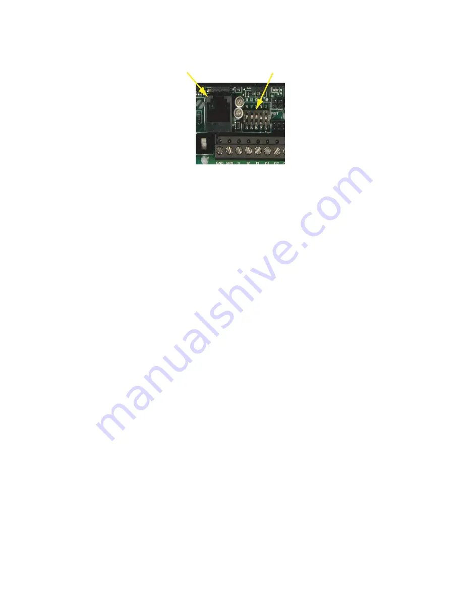
Locate the switch next to the isolation lamps behind the terminal strip. (See
Illustrations 4.)
3.
Set the switches as follows:
A. If the RS-485 connection is the End-of-Line controller, verify that both
switches 4 & 5 (A & B) are in the ON position. Otherwise, the switches
remain in the default “OFF” position.
B. If one or more inputs require a pull-up, verify that the appropriate
switches (I1–I3) is set to the default “ON” position. For devices supply-
ing their own voltage/current for passive devices, move the switch to
the “OFF” position.
4.
After you set the switches, replace the controller cover and secure it with
the screws you removed earlier.
Power Connection
Connect the 24 VAC supply voltage to the power terminal block on the lower
right side of the controller near the PWR jumper. Connect the GND side of the
transformer to the GND terminal and the AC Phase side to the AC terminal.
Power is applied to the controller when the power supply (or transformer) is
plugged in and the PWR jumper is in place. Illustration 7 shows a typical connec-
tion diagram for the controller.
Illustration 7. Typical Input Pull-up and EOL Switch Placement
Input Pull-Up/EOL
Switches
RJ–12
Conn.
Installation
KMD-7001/7002/7003 Direct Digital Controller Installation & Operation Guide


