5
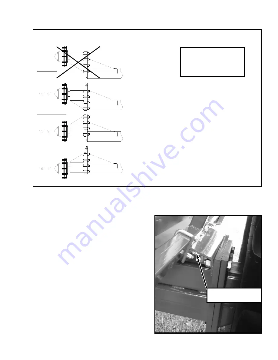
FOR MODELS 4810 & 4815
RECOMMENDED
UNUSABLE
OK FOR LOW SHIPPING
HEIGHT. UNUSABLE IN
FIELD.
RECOMMENDED
FIELD
POSITION FOR MAXIMUM
CAPACITY.
FOR MODELS 4825 & 4830
The Models 4825 & 4830
is not adjustable.
It is preset at 15’5” dump-
ing height.
DUMPING HEIGHTS
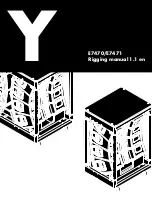
BRACE ASSEMBLY
(48-081-012)
FIGURE 6 (Brace Assembly for 4825 dump carts.)
A Brace Assembly (48-081-012) need to be
attached to the frame before the tire is mount-
ed to the axle as shown in the picture to the
right. (Figure 4)
Install the tires. Make sure the rim is turned
with the valve stem toward the outside. The
correct direction of the tire cleats should be
the OPPOSITE direction to the rear tractor
tires. Torque the wheel bolts to 400 ft. lbs.
At this point, the cart can be attached to a
towing vehicle if desired. However, it is not
fully ready for operation.
Fill the non-dumping side tire with water or
calcium chloride solution. Follow manufactur-
er’s safety precautions if using calcium chlo-
ride. Do not operate the cart until this tire has
been completely filled to capacity. The 23.1-
26 (10 ply) tires are tubeless. Support
FIGURE 5 (Dumping Heights for 4810, 4815, 4825 and 4830 dump carts)
Summary of Contents for 48 Series
Page 12: ...10 DUMP CART SPECIFICATIONS ...
Page 14: ...12 FRONT VIEW REAR VIEW ...
Page 15: ...13 LOW DUMP HIGH DUMP WEIGHT RACK DIRT SCREEN ...
Page 18: ...16 ...


