Klarity Medical Products, LLC
600 Industrial Parkway
Heath, OH 43056
T: 740.788.8107 F: 740-788-8109
www.klaritymedical.com
To be used by a qualified medical professional
IFU.BP.001.08 9/20/21
Store below
35˚C (95˚F)
35˚C
Keep in a
cool and dry
environment
Lotus NL B.V
Koningin Julianaplein 10, le Verd, 2595AA
The Hague, Netherlands
T: +31645171879 (English)
T: +31626669008 (Dutch)
EC REP
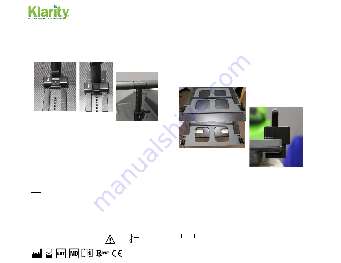
under the overhangs (the green arrow should be pointing up, away from
the patient’s head), align the green line on the base of the handle with
the lines of the desired indexing location, and engage the locking
mechanism. To adjust the height of the handle, disengage the locking
mechanism, either pull the handle up or push it down to the desired
height, and reengage the locking mechanism.
Head Rests:
The optional foam (R511) or
Silverman (R507) headrests (sold
separately) can both be used with the WingSpan™ Baseplate. The foam
headrest simply sits in the shallow recess in the middle of the
WingSpan™ Baseplate, while Silverman headrests can be indexed using
the white pins to the sides of the recess.
SBRT Full Body Vacuum Bag:
The patient’s torso can be immobilized
from below using the large vacuum bag (R7641-25BC) included in the
Klarity SBRT system. It has indexing locations at the bottom and top of
the bag. The top location indexes directly onto the WingSpan™
Baseplate and should be done first, while the bottom location indexes to
the board using one of the two SBRT Board Indexing Bars (RE-15CF)
provided with the system. With the patient in place, remove air from the
bag and form it around the patient.
NOTE
: If an optional headrest is being used, index the vacuum bag over
top of the headrest.
LOWER BODY
Knee and Foot Positioner:
The Knee and Foot Positioner includes the
Knee Positioner Device, the Foot Positioner Device, and their respective
cushions.
Knee Positioner Device:
The Knee Positioner Device (R624-SCF1-3)
indexes to the SBRT board using the two locking clips on either side. To
index, first make sure both clips are in the “Unlocked” position and
place the device at the foot of the board with the clips toward the feet
and hanging off the end. Slide the device up the board making sure that
the clips go around the lip of the
board. Move the device to the
desired location, using the
windows and indicator lines
above the locking clips for precise
locating, and move the switch on
both clips to the locked position.


