


83003502.Kc ECO_Install_Instruction_V03.odt
Page 29 of 39
7
Water connection
7.1
Pipe material
Use only the following materials for the pipes:
1. Copper is recommended
2. Stainless steel
3. PE or PVC – ensure that the appropriate steps are taken to protect the pipe along its
length.
The proper way to seal the European fittings can be done with any of following steps.
1. Pipe sealing cord. There are a number of brands available, however we use Loctite
55
2. Teflon Tape and a Anaerobic sealant.
3. Teflon Tape an Nylog sealant.
As with any sealant, the application instruction must be followed for proper use.
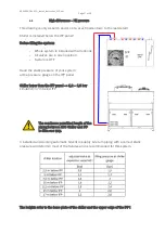
7.2
Relation of pipe diameter to distance between chiller and IFP
Use 2” (R2, DN 50 or 54-mm copper) for up to 25 meters (82 ft.) of straight pipe.
Use 2 ½” (R21/2, DN 65 or 64-mm copper) for up to 45 meters (147.6 ft.) of straight
pipe.
Distances exceeding 45 meters (147.6 ft.) are not permitted at using ECO and IFP.
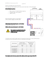
7.3
Dimensions of the connections
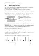
Both the coolant return (water/ethylene glycol mix) from the IFP and the coolant supply
(water/ethylene glycol) to the IFP need to have a 2” internal thread.
To connect them, use a crossover with a 2” external screw thread or preferably a fitting
with a 2” external screw thread (two crossovers are attached to the pump/chiller and two
at the IFP panel).
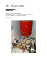
7.4
Inflow and outflow
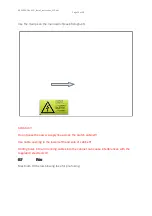
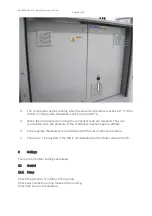
Verify that the inflow and outflow pipes are attached correctly (do not confuse).
The inflow is FROM the IFP. The outflow is TO the IFP.
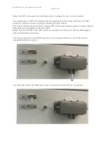
The connections are labeled (see photograph).
On the Chiller inflow and outflow use the brass-fittings.
Summary of Contents for ECO 133 L
Page 8: ...83003502 Kc ECO_Install_Instruction_V03 odt Page 8 of 39 ...
Page 9: ...83003502 Kc ECO_Install_Instruction_V03 odt Page 9 of 39 ...
Page 11: ...83003502 Kc ECO_Install_Instruction_V03 odt Page 11 of 39 ...
Page 12: ...83003502 Kc ECO_Install_Instruction_V03 odt Page 12 of 39 4 5 Dimensions in mm inch ...
Page 14: ...83003502 Kc ECO_Install_Instruction_V03 odt Page 14 of 39 Do not drill any hole into the unit ...
Page 21: ...83003502 Kc ECO_Install_Instruction_V03 odt Page 21 of 39 ...
Page 26: ...83003502 Kc ECO_Install_Instruction_V03 odt Page 26 of 39 Disassembly of the flow limiter ...
Page 37: ...83003502 Kc ECO_Install_Instruction_V03 odt Page 37 of 39 11 Overview water chiller and IFP ...