background image

14 

transporting the Machine Fig. 2.0-2.1

Slide the traction sled (1) until it stops and secure it with 
the clamping screw (A).
Lower the cutting head downwards until it stops and push 
down the lock lever (B).
Hold the mitre saw by the provided handle (19) for 
transportation.

Assembly

WARNiNG! For your own safety, never connect the plug to 
power source outlet until all assembly steps are completed 
and you have read and understood the safety and operational 
instructions.

Lift the saw from the packaging and place it on your 
work bench.

installing the Dust Bag Fig. 2.2


Place the dust bag (18) on the outlet at the upper blade 
guard.

Mounting the Clamping Jaw Fig. 2.3

Mount the clamping jaw (17) and secure it with the 
clamping screw (C). 
The clamping jaw has a quick adjustment, which is 
triggered by pressing the button (D).

Attaching the side bars


The side support bars (10) help to support the material 
when working with long work pieces. There are two 
location holes (25) for a support bar on either side of 
the table. Loosen the lock knobs on the back of the base 
at the bottom. Ensure the side bars are fully inserted 
before using them to support the work piece 
The side support bar locking knobs (H) must be tightened 
to secure the support bars in position.

Setting the tool

Note:

This tool is accurately adjusted before shipping from 
the factory. Check the following accuracy and readjust if 
necessary in order to obtain the best results in operation.

installation of the Angle Fence at 90°, Fig. 3 

Loosen the angle clamping lever (1). 

Lock the ratchet lever (2) towards the inside.

Move the cutting head to the right until it rests 
against the fence.

Tighten the angle clamping lever (1).

Test the saw blade with a 90° angle to the saw table.

If an adjustment is necessary, loosen the lock nut (3) and 
position the socket screw (4) in such a way that the saw 
blade stands at 90° to the table.  Re-tighten the lock nut.

Set the angle fence with the screw at 0.

installation of the Angle Fence at 45° Left. Fig.4

Loosen the angle clamping lever (1). 

Move the cutting head to the left until it rests against 
the fence.

Tighten the angle clamping lever (1).

Test the saw blade with a 45° angle to the saw table.

If an adjustment is necessary, loosen the lock nut (5) and 
position the socket screw (6) in such a way that the saw 
blade stands at 45° to the table.  Re-tighten the lock nut.

installation of the Angle Fence at 45° Right. Fig. 4.1

Loosen the angle clamping lever (1). 

Lock the ratchet lever (2) toward the outside.

Move the cutting head to the right until it rests 
against the fence.

Tighten the angle clamping lever (1).

Test the saw blade with a 45° angle to the saw table.

If an adjustment is necessary, loosen the lock nut (5) and 
position the socket screw (6) in such a way that the saw 
blade stands at 45° to the table.  Re-tighten the lock nut.

installation of the Contact Surface, Fig. 5

•  Lower the cutting head and push in the lock pin. Make 

sure the table is in 0 mitre position.

•  Place a combination square against the fence and next 

to the saw blade.

•  Loosen the two screws (7) if the saw blade does not 

touch the protractor. 

•  Adjust the fence so that the fence has full contact with 

the square. Tighten the screws.

Adjusting the Laser Line Fig 5.1-5.2

To adjust the laser beam, take a board (approx. 200 
mm x 300 mm) mark a line at the right angle and 
place the board on the contact surface of the table.

Align the mark to the centre of the saw blade and 
clamp it firmly with the clamping shoe.

Turn the laser on with the switch (23 Fig.1).

To adjust the laser line, pull the cover (A) and loosen 
the slotted screw (B).

Now move the laser unit until the laser line fits in 
with the marked line.

Fine adjustment can be done with the two slotted 
screws (C) and (D)

Note: 

You can adjust the laser line so that it runs on the side 
or in the middle of the cut.

Tighten the slotted screw again and slide the housing's 
cover back on the laser unit.

Caution! 

Do not stare directly into the laser beam, read 

the safety instructions for laser light.

Connecting to the Power Supply

Check that the power supply and outlet used are in ac-
cordance with your mitre saw. Have a look at the rat-
ing plate of the motor or the rating on the mitre saw. 
Any changes should always be carried out by a qualified 
electrician.
This is a double insulated tool which eliminates the need 
for an earthed power supply system.

WARNiNG! Avoid contact with the terminals on the plug when 
installing (removing) the plug to (from) the power supply 
outlet. Contact will cause a severe electrical shock.

Summary of Contents for MS305DB

Page 1: ...mpund Mitre Saw Translation from the original instruction manual FR Scie à onglets radiales Traduction du manuel d origine IT Troncatrice radiale Traduzione del manuale di istruzioni originale D Kapp Zugsäge 4 10 GB Slide compund Mitre Saw 11 17 FR Scie à onglets radiales 18 24 IT Troncatrice radiale 25 31 MS305DB ...

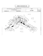
Page 2: ...g 2 A 19 15 15 1 B Fig 2 1 B Fig 2 3 D 17 C Fig 5 7 7 7 7 Fig 3 1 4 3 Fig 4 1 5 6 Fig 4 1 5 6 1 2 Fig 5 1 A Fig 5 2 D B C Fig 1 3 22 5 4 23 6 15 16 11 24 12 15 10 8 9 14 10 9 17 21 20 1 19 19 18 22 3 5 4 2 7 13 25 H ...

Page 3: ...Fig 6 2 1 Fig 6 1 3 2 2 1 Fig 6 2 3 3 2 1 Fig 7 B A Fig 7 1 C D Fig 7 2 7 8 Fig 7 3 E Fig 7 4 G F ...

Page 4: ...achtet wer den An der Maschine dürfen nur Personen arbeiten die im Gebrauch der Maschine unterwiesen und über die damit verbundenen Gefahren unterrichtet sind Das ge for der te Mindestalter ist einzuhalten Neben den in dieser Bedienungsanweisung enthaltenen Si cherheitshinweisen und den besonderen Vorschriften Ih res Landes sind die für den Betrieb von Holzbearbeitungs maschinen allgemein anerkann...

Page 5: ...der Gasen Schützen Sie sich gegen Stromschlag Vermeiden Sie den Körperkontakt mit geerdeten Oberflächen Verweigern Sie unbefugten Personen den Zutritt Er lauben Sie anderen Personen speziell Kindern nicht die Beteiligung an derArbeit das Berühren der Werk zeuge oder der Verlängerungskabel und auch nicht den Zutritt zum Arbeitsplatz Schließen Sie unbenutzte Werkzeuge weg Werkzeuge die z Zt nicht be...

Page 6: ...ahr dar obwohl das Starren in den Strahl zu einer Blitzerblindung führen kann Warnung Blicken Sie nicht direkt in den Laserstrahl da dies eine Gefahr darstellen könnte Beachten Sie die folgenden Sicherheitsvorschriften Der Laser darf nur in Übereinstimmung mit den Vor schriften des Herstellers verwendet und gewartet wer den Richten Sie den Strahl ausschließlich auf das Werk stück und niemals auf e...

Page 7: ...ie sie auf Ihre Werkbank Installation des Staubsackes Fig 2 2 Stecken Sie den Staubsack 18 auf die Auslassöffnung am oberen Sägeblattschutz Montage der Spannbacke Fig 2 3 Montieren Sie die Spannbacke 17 und befestigen diese mit der Klemmschraube C Die Spannbacke hat eine Schnellverstellung die durch drücken am Knopf D ausgelöst wird Anbringen der seitlichen Verbreiterungen Die seitlichen Verbreite...

Page 8: ...ualifizierten Elektriker zur Mindestdrahtgröße des Verlängerungskabels Das Verlängerungskabel muß an einem Ende einen geer deten Stecker der in die Stromsteckdose passt und am anderen Ende eine geerdete Steckdose haben die zum Stecker der Maschine passt Werkzeugbetrieb WARNUNG Schließen Sie den Stecker nie an der Stromquelle an bevor alle Installationen und Einstellungen abgeschlos sen sind und Si...

Page 9: ...sten nicht benutzt werden Da die meisten Zimmer nicht über exakte 90 Winkel verfügen ist eine Feineinstellung notwendig Nehmen Sie immer einen Testschnitt vor um zu sichern dass der Winkel korrekt ist Schnitt mit Zugfunktion Fig 6 WARNUNG 1 Ziehen Sie nie den Schneidkopfsatz und das rotierende Sägeblatt während des Sägens auf sich zu Das Sägeblatt könnte am Werkstück heraufklettern wodurch Schneid...

Page 10: ...ellen durch unsachgemäße Befestigung oder Füh rung der Anschlussleitung Schnittstellen durch Überfahren der Anschlussleitung Isolationsschäden durch Herausreißen aus der Wandsteck dose Risse durch Alterung der Isolation Solch schadhafte Elektro Anschlussleitungen dürfen nicht verwendet werden und sind auf Grund der Iso la ti ons schä den lebensgefährlich Elektrische Anschlussleitungen regelmäßig a...

Page 11: ...y each operator prior to starting the work Only persons who have been trained in the use of the machine and have been informed on the related dangers and risks are allowed to use the machine The required minimum age must be met In addition to the safety notes contained in the present operating instructions and the special regulations of your country the generally recognized technical rules for the...

Page 12: ...r reach Keep proper footing and balance at all time Maintain tools with care Keep cutting tools sharp and clean for better and safer performance Follow instruc tions for lubricating and changing accessories Inspect power cables periodically and if damaged have them replaced by an authorised service facility Inspect ex tension cables periodically and replace if damaged Keep handles dry clean and fr...

Page 13: ...dimensions must be adhered to Relevant accident prevention regulations and other gene rally recognized safety technical rules must also be adhered to The machine may only be used maintained and op erated by persons familiar with it and instructed in its operation and procedures Arbitrary alterations to the machine release the manufacturer from all responsi bility for any resulting damages The mach...

Page 14: ...angle to the saw table If an adjustment is necessary loosen the lock nut 5 and position the socket screw 6 in such a way that the saw blade stands at 45 to the table Re tighten the lock nut Installation of the Angle Fence at 45 Right Fig 4 1 1 Loosen the angle clamping lever 1 2 Lock the ratchet lever 2 toward the outside 3 Move the cutting head to the right until it rests against the fence 4 Tigh...

Page 15: ... dle Activate the switch then press the blade guard lock lever to lower the cutting head down Compound Cut A compound cut is a combination of mitre cut and bevel cut Refer to the above procedures to perform this cut Base Moulding Base moulding can be cut vertically against fence or flat on the table Follow the table below for reference Settings Vertical position Back of moulding is flat against th...

Page 16: ...he guiding lever A 7 0 3 Remove the slotted screw C on the saw blade guard D 7 1 4 Unlock the lower saw blade guard 7 by pressing the clamping lever 3 Fig 1 5 Lift the lower saw blade guard to release the saw blade 7 2 6 Press saw blade lock E turn the saw blade 8 until the lock clicks into place 7 3 7 Loosen the saw blade lock screw F using the supplied key G caution left hand thread 7 4 8 Remove...

Page 17: ... current of the motor Data recorded on the machine s rating plate Data recorded on the switch s rating plate If a motor has to be returned it must always be dis patched with the complete driving unit and switch EC declaration of conformity We hereby declare Scheppach Fabrikation von Holzbearbeitungsmaschinen GmbH Günzburger Strasse 69 D 89335 Ichenhausen that the machine indicated below on the bas...

Page 18: ...e Elles doivent être lues par chaque opérateur avant qu il ne commence à travailler et elles doivent être minutieusement respectées Seules des personnes ayant été instruites sur l utilisation de la machine et informées des dangers possibles ont le droit de travailler sur la machine Il faut respecter l âge minimum En plus des consignes de sécurité figurant dans les pré sentes instructions de servic...

Page 19: ...quipement de protection Utiliser des lu nettes de protection Si la coupe fait de la poussière porter un couvre face ou un masque anti poussières Brancher l équipement de dépoussiérage S il est pos sible de brancher un dispositif d extraction et de col lecte des poussières veiller à le faire et à s en servir comme il convient Traiter le câble avec soin Ne jamais tirer sur le câble pour l enlever de...

Page 20: ...ont acceptables Des tôles brillantes réfléchissantes ou des matériaux similaires ne conviennent pas au Laser car la surface réfléchissante pourrait renvoyer le rayon vers l utilisateur Ne remplacez pas l unité Laser par une autre d un type différent Les réparations doivent être effectuées par le constructeur ou une entreprise spécialisée Attention Vous ne devez utiliser que les outils et procé dur...

Page 21: ... 2 3 Installez l étau de serrage l 17 et fixez le avec la vis de serrage C L étau dispose d un ajustement rapide qui est activé en appuyant sur le bouton D L attache des rallonges latérales Les extensions latérales 10 aident à soutenir les longues pièces de bois Il y a deux emplacements de chaque côté de la base 25 Insérer les extensions et serrer les vis à l arrière de la base Assurez vous que le...

Page 22: ...ENTION Pour éviter d être blessé par des projections de matériaux débrancher la scie pour l empêcher de se mettre en marche accidentellement et enlever les petits morceaux de matériaux Coupe de refend Fig 6 Pour la coupe de refend faire glisser la tête de coupe vers l arrière aussi loin qu elle peut aller et bloquer le chariot 1 à l aide de la manette de blocage 2 Coupe d onglet Assurez vous que l...

Page 23: ...terminer la coupe Relâcher la gachette et attendre que la lame ait fini de tourner avant de relever la tête de coupe Réglage de profondeur normal Fig 6 1 Position de la scie à 5 mm au dessous du plateau de la table séparer les pièces à usiner Butée de profondeur 1 à mettre en place La vis de butée 2 est en utilisation la vis de réglage 3 n a pas de fonction Réglage de profondeur amovible Fig 6 2 F...

Page 24: ...teur pendant la vérification Les câbles de branchement électrique doivent corres pondre à la réglementation en vigueur dans votre pays Moteur monophasé La tension du secteur doit correspondre aux indica tions portées sur la plaque signalétique du moteur Les câbles de rallonge d une longueur maximale de 25m doivent présenter une section transversale de 1 5 mm2 ceux d une longueur supérieure à 25 m ...

Page 25: ... dei relativi pericoli e rischi che essa comporta Va rispettata l età minima prescritta In aggiunta alle norme di sicurezza contenute nelle pre senti istruzioni per l uso e alle specifiche norme di sicu rezza del suo Paese devono altresì essere rispettate le regole tecniche generalmente riconosciute per l utilizzo di macchine per la lavorazione del legno m In queste istruzioni per l uso abbiamo se...

Page 26: ...olvere Se sono disponibili apparecchi per aspirare la polvere accertarsi che siano collegati e che siano usati cor rettamente Fare attenzione ai cavi Non tirare mai un cavo per staccarlo dalla presa Tenere i cavi lontano da fonti di calore olio e bordi taglienti Fissare bene il mezzo di lavoro Dove possibile fissare il mezzo di lavoro con morsetti o con una morsa a vite E più sicuro del fissaggio ma...

Page 27: ... gli utensili di messa a punto o regolazione e i relativi procedimenti descritti in questo manuale La mancata osservanza di queste regole può causare irradiazioni pericolose m Utilizzo a norma Le macchine testate con marchio CE soddisfano tutti i re quisiti previsti dalle normative CE per i macchinari e dalle norme relative ad ogni macchina Usare la macchina solo in condizioni perfette per gli sco...

Page 28: ...itivo di regolazione veloce che si aziona premendo il pulsante D Montare le barre laterali Le barre di supporto laterale 10 aiutano a sostenere il materiale quando si lavora con pezzi lunghi Ci sono due fori di posizione 25 per la barra di supporto su ciascuno dei lati del tavolo Allentare le manopole di bloccaggio sulla parte posteriore bassa della base Assicurarsi che le barre laterali siano com...

Page 29: ...ma del cavo di prolunga Il cavo di prolunga deve presentare a un estremità una spina messa a terra adeguata alla presa e all altra estre mità una presa messa a terra adeguata alla presa della macchina Azionamento dell utensile AVVERTENZA Non collegare mai la spina a una fonte di corrente prima di avere terminato l installazione e avere letto e compreso le avvertenze relative alla sicurezza e le is...

Page 30: ...ueste battute speciali non possono essere utilizzate con bordature decorative da soffitto a 45 Poiché gran parte delle stanze non presenta angoli esatti a 90 è necessaria una regolazione di precisione Effettuare sempre un taglio di prova per verificare l esattezza dell angolo Taglio con funzione di trazione AVVERTENZA 1 Non tirare mai verso di sé il gruppo della testa di taglio e la lama rotante du...

Page 31: ... dovuti al calpestio del cavo di collegamento Danni all isolamento causati strappando il cavo e la spina dalla presa Strappi dovuti all usura dell isolamento I cavi elettrici danneggiati non devono essere utilizzati in quanto i danni all isolamento li rendono estremamente pericolosi Controllare regolarmente l integrità dei cavi elettrici As sicurarsi che il cavo sia scollegato dalla presa durante ...

Page 32: ...32 ...

Page 33: ......

Page 34: ...öltek javításokat A jótállási elismervény csak a számlával együtt érvényes Garancija SLOWAKEI Na toto zariadenie sa vzťahuje záruka 24 mesiacov 1 Záruka sa vzťahuje len na chyby materiálu a na konštrukčné chyby Chybné časti sú vymenené zadarmo zákazník zaplatí len za cenu práce Záruku poskytujeme len na originálne diely Scheppach 2 Záruka sa nevzťahuje na poškodenie pri prevoze opotrebovanie súčia...

Reviews: