background image

4

Electrical Requirements

If codes permit and a separate ground wire is used, it is 
recommended that a qualified electrical installer determine that 
the ground path and wire gauge are in accordance with local 
codes.

Do not use an extension cord.

Be sure that the electrical connection and wire size are adequate 
and in conformance with the National Electrical Code, ANSI/
NFPA 70-latest edition and all local codes and ordinances. 

A copy of the above code standards can be obtained from:

National Fire Protection Association

1 Batterymarch Park

Quincy, MA 02169-7471

WARNING:

 Improper connection of the equipment-grounding 

conductor can result in a risk of electric shock. Check with a 
qualified electrician or service technician if you are in doubt as to 
whether the appliance is properly grounded. Do not modify the 
power supply cord plug. If it will not fit the outlet, have a proper 
outlet installed by a qualified electrician.

Electrical Connection

To properly install your range, you must determine the type of 
electrical connection you will be using and follow the instructions 
provided for it here.

Range must be connected to the proper electrical voltage 
and frequency as specified on the model/serial/rating plate. 
The model/serial/rating plate is located behind the control 
panel. Refer to the figures in “Product Dimensions” in the 
“Location Requirements” section.

This range is manufactured with the neutral terminal 
connected to the cabinet. Use a 3-wire, UL listed, 40- or 
50-amp power supply cord (pigtail) (see the following Range 
Rating chart). If local codes do not permit ground through the 
neutral, use a 4-wire power supply cord rated at 250 volts, 
40- or 50-amps and investigated for use with ranges.

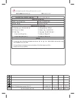
*The NEC calculated load is less than the total connected load 

listed on the model/serial/rating plate.

**If connecting to a 50-amp circuit, use a 50-amp rated cord with 

kit. For 50-amp rated cord kits, use kits that specify use with a 
nominal 1

³⁄₈

" (34.9 mm) diameter connection opening.

A circuit breaker is recommended.

The range can be connected directly to the circuit breaker 
box (or fused disconnect) through flexible or nonmetallic 
sheathed, copper or aluminum cable. See the “Electrical 
Connection - U.S.A. Only” section.

Allow 2 to 3 ft (61.0 cm to 91.4 cm) of slack in the line so that 
the range can be moved if servicing is ever necessary.

A UL listed conduit connector must be provided at each end 
of the power supply cable (at the range and at the junction 
box).

Wire sizes and connections must conform with the rating of 
the range.

The wiring diagram is located on the Tech Sheet.

The Tech Sheet is located on the back of the range inside a 
clear plastic bag.

If connecting to a 4-wire system:

This range is manufactured with the ground connected to the 
neutral by a link. The ground must be revised so the green 
ground wire of the 4-wire power supply cord is connected to the 
cabinet. See “Electrical Connection - U.S.A. Only” section.

Grounding through the neutral conductor is prohibited for new 
branch-circuit installations (1996 NEC); mobile homes; and 
recreational vehicles, or an area where local codes prohibit 
grounding through the neutral conductor.

When a 4-wire receptacle of NEMA Type 14-50R is used, a 
matching UL listed, 4-wire, 250-volt, 40- or 50-amp, range power 
supply cord (pigtail) must be used. This cord contains 4 copper 
conductors with ring terminals or open-end spade terminals with 
upturned ends, terminating in a NEMA Type 14-50P plug on the 
supply end. 

The fourth (grounding) conductor must be identified by a green or 
green/yellow cover and the neutral conductor by a white cover. 
Cord should be Type SRD or SRDT with a UL listed strain relief 
and be at least 4 ft (1.22 m) long.

The minimum conductor sized for the copper 4-wire power 
cord are:

40-amp circuit
2 No.-8 conductors
1 No.-10 white neutral
1 No.-10 green grounding

If connecting to a 3-wire system:

Local codes may permit the use of a UL listed, 3-wire, 250-volt, 
40- or 50-amp range power supply cord (pigtail). This cord 
contains 3 copper conductors with ring terminals or open-end 
spade terminals with upturned ends, terminating in a NEMA Type 
10-50P plug on the supply end. Connectors on the appliance end 
must be provided at the point the power supply cord enters the 
appliance. This uses a 3-wire receptacle of NEMA Type 10-50R.

Range Rating*

Specified Rating of 
Power Supply Cord Kit 
and Circuit Protection

120/240 Volts

120/208 Volts

Amps

8.8 - 16.5 KW
16.6 - 22.5 KW

7.8 - 12.5 KW
12.6 - 18.5 KW

40 or 50**
50

4-wire receptacle (14-50R)

3-wire receptacle (10-50R)

Summary of Contents for YKFED500ESS

Page 1: ...ed or seriously injured if you don t immediately You can be killed or seriously injured if you don t follow All safety messages will tell you what the potential hazard is tell you how to reduce the chance of injury and tell you what can happen if the instructions are not followed Your safety and the safety of others are very important We have provided many important safety messages in this manual ...

Page 2: ...racket shipped with the range see Install Anti Tip Bracket section Grounded electrical supply is required See Electrical Requirements section IMPORTANT To avoid damage to your cabinets check with your builder or cabinet supplier to make sure that the materials used will not discolor delaminate or sustain other damage This range has been designed in accordance with the requirements of UL and CSA In...

Page 3: ...NOTE 24 61 0 cm minimum when bottom of wood or metal cabinet is covered by not less than 0 64 cm flame retardant millboard covered with not less than No 28 MSG sheet steel 0 015 0 4 mm stainless steel 0 024 0 6 mm aluminum or 0 020 0 5 mm copper 30 76 2 cm minimum clearance between the top of the cooking platform and the bottom of an uncovered wood or metal cabinet A 35 90 8 cm 0 3 cm cooktop heig...

Page 4: ...num cable See the Electrical Connection U S A Only section Allow 2 to 3 ft 61 0 cm to 91 4 cm of slack in the line so that the range can be moved if servicing is ever necessary A UL listed conduit connector must be provided at each end of the power supply cable at the range and at the junction box Wire sizes and connections must conform with the rating of the range The wiring diagram is located on...

Page 5: ... may be done with the range on its back or with the range supported on 2 legs after the range has been placed back to a standing position NOTE To place range back up into a standing position put a sheet of cardboard or hardboard in front of range Using 2 or more people stand range back up onto the cardboard or hardboard 2 Adjust the leveling legs to the correct height Leveling legs can be loosened...

Page 6: ...spond to the bracket holes of the determined mounting method See the following illustrations 5 Using two 12 x 1 Phillips head screws provided mount anti tip bracket to the wall or floor A Anti tip bracket B Mark edge of range C 2 4 cm WARNING Tip Over Hazard A child or adult can tip the range and be killed Install anti tip bracket to floor or wall per installation instructions Slide range back so ...

Page 7: ...e cord conduit plate on bottom of range Allow enough slack to easily attach the wiring to the terminal block Tighten strain relief screw against the power supply cord Power Supply Cord Direct Wire WARNING Electrical Shock Hazard Disconnect power before servicing Use a new 40 amp power supply cord Plug into a grounded outlet Failure to follow these instructions can result in death fire or electrica...

Page 8: ...nstallation following instructions for your type of electrical connection 4 wire recommended 3 wire if 4 wire is not available Electrical Connection Options A Removable retaining nut B Strain relief A B If your home has And you will be connecting to Go to Section 4 wire receptacle NEMA type 14 50R A UL listed 250 volt minimum 40 amp range power supply cord 4 wire connection Power supply cord 4 wir...

Page 9: ...lock posts with 10 32 hex nuts 7 Securely tighten hex nuts NOTE For power supply cord replacement only use a power cord rated at 250 volts minimum 40 amps or 50 amps that is marked for use with nominal 1 3 5 cm diameter connection opening with ring terminals and marked for use with ranges 8 Replace terminal block access cover 9 Slide range back so rear range foot is under the anti tip bracket See ...

Page 10: ... insulation back 1 2 5 cm from the end of each wire 2 Allow enough slack in the wire to easily attach to the wiring terminal block 3 Complete electrical connection according to your type of electrical supply 4 wire or 3 wire connection 4 wire Connection Direct Wire Use this method for New branch circuit installations 1996 NEC Mobile homes Recreational vehicles In an area where local codes prohibit...

Page 11: ... if local codes permit connecting ground conductor to neutral supply wire 1 Pull the conduit through the hole and conduit plate on bottom of range Allow enough slack to easily attach the wiring to the terminal block 2 Attach terminal lugs to line 1 black bare green ground and line 2 red wires Loosen do not remove the setscrew on the front of the terminal lug and insert exposed wire end through bot...

Page 12: ...for contact information 6 Repeat steps 1 and 2 to ensure that the range foot is engaged in the anti tip bracket If the rear of the range lifts more than 1 3 cm off the floor without resistance the anti tip bracket may not be installed correctly Do not operate the range without anti tip bracket installed and engaged Please reference the Assistance or Service section of the Use and Care Guide or the...

Page 13: ...r maintenance 4 Slide range back so rear range foot is under anti tip bracket 5 Refer to the Verify Anti Tip Bracket Is Installed and Engaged section to verify engagement 6 Check that range is level 7 Reconnect power WARNING Tip Over Hazard A child or adult can tip the range and be killed Install anti tip bracket to floor or wall per installation instructions Slide range back so rear range foot is...

Page 14: ...14 Notes ...

Page 15: ...15 Notes ...

Page 16: ...W10694065A 2014 All rights reserved 9 14 Printed in U S A ...

Reviews: