1
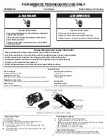
FOR SERVICE TECHNICIAN’S USE ONLY
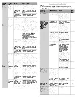
NOTE:
This sheet contains important Technical Service Data.
W10880570A Tech Sheet Do Not Remove Or Destroy
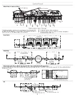
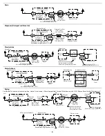
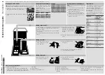
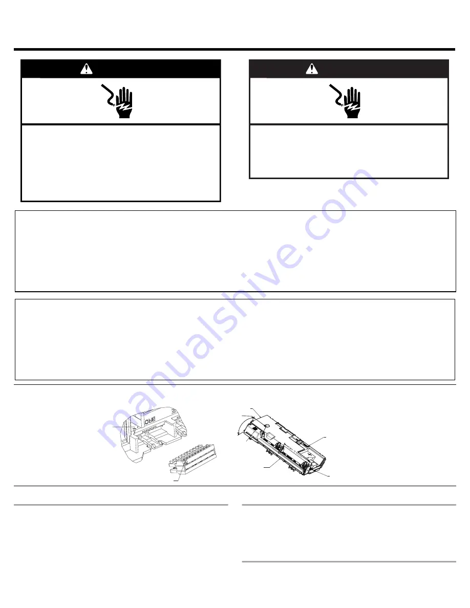
Control Assembly
Meter Check of Loads and Fuses
Fuse Service Check:
F8 = Motor Fuse
F9 = Small-triac Load Fuse
Check operation of loads during the Service Diagnostics cycle.
■
If any of the triac loads work, F9 Fuse is OK.
■
If all triac loads fail to work, F9 Fuse could be open. See “Fuse
Resistance Check.”
■
If Wash Motor does not work, F8 Fuse could be open. See “Fuse
Resistance Check.”
Fuse Resistance Check:
1.
Unplug the dishwasher or disconnect power.
2.
Measure resistance of F8 Fuse and/or F9 Fuse.
NOTE:
Fuses are on the bottom of the Control Board but can be checked
from the top side. See “Control Pinout” diagram.
■
If resistance is <3
?
) then fuse is OK.
■
If resistance is >3
?
) then fuse is open.
What To Do If Fuse Open:
Inspect and check resistance of all loads on fuse. If any loads are open,
shorted, or have evidence of overheating or pinched wires, replace them.
DANGER
Electrical Shock Hazard
Only authorized technicians should perform diagnostic
voltage measurements.
After performing voltage measurements, disconnect
power before servicing.
Failure to follow these instructions can result in death
or electrical shock.
WARNING
Electrical Shock Hazard
Disconnect power before servicing.
Replace all parts and panels before operating.
Failure to do so can result in death or electrical shock.
SPECIFICATIONS
Electrical Supply:
(Under load) 60 Hz, 120 VAC
Lower Spray Arm Rotation:
12 to 40 rpm
Supply Water Flow Rate:
To fill 2 qt (1.9 L) in 27 seconds, 120 psi maximum, 20 psi minimum.
Upper Spray Arm Rotation:
12 to 30 rpm
Supply Water Temperature:
120°F (49°C) (Before starting a cycle, run water from sink faucet until hot.)
REPAIR KITS
Water Charge:
0.9 gal. (3.5 L) Approximate
Vinyl Touch-up Kits:
675576 (Blue), 676453 (White), 676455 (Gray)
Voltage Measurement Safety Information
When performing live voltage measurements, you must do the following:
■
Verify the controls are in the off position so that the appliance does not start when energized.
■
Allow enough space to perform the voltage measurements without obstructions.
■
Keep other people a safe distance away from the appliance to prevent potential injury.
■
Always use the proper testing equipment.
■
After voltage measurements, always disconnect power before servicing.
Pin 1
Rast Connector Pinout
Pin 1
Control
Assembly
Pinch to
release
Rotate
Connector Box
Connector Brace
(To remove, pinch
arms and rotate)
Control panel snap
locks control in place
Buttons on bottom
of control housing
slide into keyhole
slots on control
panel to support
the control

