background image

4-7

7.

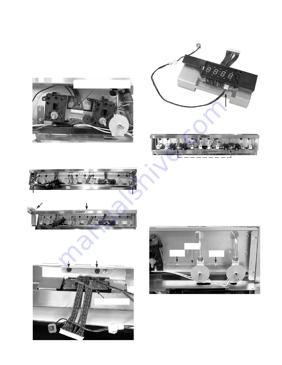
To remove a clock:

a) Remove the control panel from the unit

(see step 3 on page 4-4 for the proce-
dure).

b) Disconnect  the  12-wire  quick  discon-

nect  from  the  thermostat  &  selector
switch assembly.

c) Remove the two left and two right screws

from the front panel frame and remove
the frame from the unit.

d) Remove the two screws from the clock

assembly bracket and remove the as-
sembly from the frame.

e) Disconnect the 2-wire connector from

the clock board.

12-Wire Quick Disconnect

2 Left Screws

2 Right Screws

Front Frame

Remove

Clock Bracket Screws

Clock Assembly

2-Wire Connector

Clock Assembly

a) Remove the control panel from the unit

(see step 3 on page 4-4 for the proce-
dure).

b) Remove  the  front  panel  frame  (see

step 7 for the procedure).

c) Remove the two hex-head screws from

the  left  and  right  shields  and  remove
the shields.

8.

To remove the left or right thermostat &
selector switch assembly:

Thermostat & Selector Switch Assemblies

Shield

Screw

Screw

Continued on the next page.

Summary of Contents for KDRP487MSS - 48" Pro-Style Dual Fuel Range W

Page 1: ...TECHNICAL EDUCATION JOB AID 4317355 KAC 38 48 Dual Fuel Slide In Range Model KDRP487MSS ...

Page 2: ...e range The Wiring Diagram and Strip Circuits used in this Job Aid are typical and should be used for training purposes only Always use the Wiring Diagram supplied with the product when servicing the unit GOALS AND OBJECTIVES The goal of this Job Aid is to provide detailed information that will enable the service technician to properly diagnose malfunctions and repair the KitchenAid 48 Dual Fuel S...

Page 3: ...ving The Control Panel And Components 4 4 Removing An Oven Door Latch Assembly A Control Panel Thermal Fuse 4 10 Removing The Main Electronic Control 4 12 Removing A Halogen Lamp Assembly 4 14 Removing A Broil Element 4 15 Removing An Oven Temperature Sensor 4 16 Removing A Rear Panel 4 17 Removing A Convection Bake Element Fan Motor Assembly 4 18 Removing A Blower Motor Assembly 4 20 Removing The...

Page 4: ...perature Sensor 5 4 Oven Shutdown Thermal Fuse 5 5 Convection Fan Motor 5 5 Broil Element 5 6 Hidden Bake Element 5 6 Ignition Switches 5 7 DIAGNOSIS TROUBLESHOOTING 6 1 Diagnosis 6 1 Failure Error Display Codes 6 1 Control Panel Tests 6 2 Oven Shutdown Thermal Fuse 6 2 Relay Logic 6 3 WIRING DIAGRAM STRIP CIRCUITS 7 1 Wiring Diagram 7 1 Strip Circuits 7 2 ...

Page 5: ...ROFESSIONAL COMMERCIAL S STANDARD T TEMPERED GLASS TOP CAPACITY SIZE SERIES CONFIGURATION 1ST POSITION 2ND POSITION 1 DROP IN 0 30 WIDE 2 DROP IN SLIDE IN COMBO 6 36 WIDE 3 SLIDE IN 8 48 WIDE 4 COMMERCIAL 5 STANDARD 7 EYE LEVEL 8 48 9 60 FEATURES 0 STANDARD FEATURES 2 PLUS FEATURES OR SEALED BURNERS W GRILL CONVECTION OVEN 3 SEALED BURNERS W GRIDDLE CONVECTION OVEN 4 SEALED BURNERS W GRILL GRIDDLE...

Page 6: ...SERIAL NUMBER LABEL AND TECH SHEET LOCATIONS The Model Serial Number label and Tech Sheet locations are shown below Tech Sheet Location Behind Control Panel Model Serial Number Location On Oven Frame Behind Door ...

Page 7: ...TU Gas Right Rear Output BTU Nat LP 15000 BTU 12000 BTU Gas Left Rear Output BTU Nat LP 15000 BTU 12000 BTU Gas Center RF Output BTU Nat LP 15000 BTU 12000 BTU Gas Center RR Output BTU Nat LP 15000 BTU 12000 BTU Gas Center LF Output BTU Nat LP 15000 BTU 12000 BTU Gas Center LR Output BTU Nat LP 15000 BTU 12000 BTU Gas Ignition Cooktop Electronic Gas Valves Degrees 210 degrees Main Single Oven Cycl...

Page 8: ...00 W 1200 W Accessories Backsplash Part Comment 9 Standard Island Trim Part Comment Standard LP Conversion Kit Part Comment Standard Stainless Steel Cleaner Included Wok Ring Optional Part 8284965 Miscellaneous Product Literature Installation Instructions Part Comment 8301285 Conversion 8301283 Service Manual Part Number 4317355 Tech Sheet Part Number 8301281 Use Care Guide Oven Part Comment 83012...

Page 9: ... for solid state touch control system and Magnetron tube in combination ovens to correct defects in materials or workmanship SIXTH THROUGH TENTH YEAR LIMITED WARRANTY ON RANGES AND BUILT IN OVENS PORCELAIN OVEN CAVITY INNER DOOR On ranges and built in ovens only in the sixth through tenth years from the date of purchase when this appliance is operated and maintained according to instructions attac...

Page 10: ...1 6 NOTES ...

Page 11: ... or electrical shock Fire Hazard Shut off gas supply line valve Make all conversions before turning gas supply valve back on Failure to follow these instructions can result in explosion fire or other injury NOTE Gas conversion from natural to L P gas must be done by a qualified installer 2 To convert the cooktop burners for use with L P gas a Remove the grates and burner caps b Remove the two T 20...

Page 12: ...er the gas con version is the same a Remove the bottom trim from the range b Remove the three screws from each end of the bottom trim and remove the trim c Use an 8 mm socket and carefully re move the orifice spud from each of the four burners Surface Burner Orifice 8mm Socket 3 Bottom Trim Screws small red small red 48 121 92 cm models large blue large blue large blue large blue large blue large ...

Page 13: ...ap Set For Use With N Natural Gas Plastic Cap L P Gas d Install the loop on the plastic cap over the natural gas side of the conversion cap e Install the plastic cap and the conver sion cap on the gas distribution valve with the L P side facing up you will see LP stamped inside the cap as shown below 4 Reinstall the bottom trim 5 Turn the gas supply valve handle on Gas Valve Handle To On Position ...

Page 14: ... the gas valve stem and note the small screw Insert a small screw driver into the gas valve stem and fit it in the screw slot ADJUSTING FOR THE PROPER FLAME c Hold the gas valve stem with a pair of pliers and turn the screw in either di rection until the flame size is approxi mately 1 4 high d Replace the control knob e Turn the control knob from HI to LO and check to make sure that it remains ad ...

Page 15: ...ainst the wall molding or cabi net and the bracket template is in the location where the anti tip bracket will be installed 3 Tape the template to the floor Template NOTE For mounting to a wood floor proceed to step 4 For concrete or ceramic floors pro ceed to step 5 Template Tip Over Hazard A child or adult can tip the range and be killed Connect anti tip bracket to rear range foot Reconnect the ...

Page 16: ...bracket template to mark the hole locations to be drilled b Use a 3 16 drill bit and drill the two holes c Remove the template from the floor d Tap the two plastic anchors into the mounting holes with a hammer e Line up the two mounting holes in the anti tip bracket with the two holes you just drilled in the floor f Use the two screws that were supplied and fasten the anti tip bracket to the floor...

Page 17: ... from the control board power transformer It com municates between the secondary oven elec tronic controls with 5 volt pulses from the main control s P9 1 yellow wire and uses the P9 3 orange wire as a ground reference If the main control malfunctions an F04 error code will be indicated in the clock displays Refer to the Tech Sheet that is supplied with the unit for additional information As you t...

Page 18: ...ve a double line break relay that is a safety relay to control the circuit to the L2 side of the line L2 L1 GRN BK BK P4 1 P4 2 P7 4 P7 2 P7 3 P3 1 P1 3 P5 4 P5 1 P5 3 P1 1 P1 5 P7 1 R R P7 5 DOUBLE LINE BREAK RELAY P9 1 P9 3 Y ORG P3 2 P3 3 P3 2 P3 3 P9 1 P9 3 Y ORG LS2 LS1 BK P8 1 P8 3 P8 2 P8 4 BK BK W1 GRN BK BK P4 1 P4 2 P7 4 P7 2 P7 3 P3 1 P1 3 P5 4 P5 1 P5 3 P1 1 P1 5 P7 1 R R BU BROIL OR D...

Page 19: ... Left Thermostat Selector Switch Assemby Spark Modules Main Electronic Control Oven Temperature Sensor On Rear Panel Oven Light Switch Door Latch Assembly Hidden Bake Element Hidden Bake Element Door Gasket Left Electronic Control Blower Motor Broil Element Control Power Transformer Blower Motor Broil Element Tech Sheet Oven Shutdown Thermal Fuse On Rear Panel Halogen Lamp Control Power Transforme...

Page 20: ...ly line valve before servicing Check all gas line connections and replace all parts and panels before operating Failure to do so can result in explosion fire or other injury 4 To remove the cooktop a Remove the two T 20 torx screws from each of the burner heads and remove the heads from the cooktop 3 Remove the burner caps from the burner heads b Remove the screws from the front and rear corners o...

Page 21: ...o hex head screws from the burner base bracket and position the assembly so that you can access the ignitor screw d Remove the screw from the ignitor and removetheignitorfromtheburnerbase e Remove the two hex head screws from the burner base and remove the base from the bracket Gas Line Ignitor Wire Screw Screw Ignitor Screw Burner Base Screws ...

Page 22: ...the gas valves selec tor switches and thermostats b Remove the two indicated machine screws from each bezel of the two thermostats selectorswitches NOTE The thermostat and selector switch for each oven is an assembly and is mounted to the control panel with two machine screws Leave the remaining bezel sheet metal screws in place It is not necessary to remove them c Lower the control panel so the s...

Page 23: ...nectors CANCEL Pushbutton ENTER Pushbutton a Remove the control panel from the unit see step 3 on page 4 4 for the proce dure b Disconnect the wires from the spark module terminals c Remove the two hex head screws from the spark module and remove the mod ule Spark Modules Left Right Brown Spark Module Screw Brown Yellow Yellow 2 Red 2 White Blue 2 Green Screw a Remove the control panel from the un...

Page 24: ...gas valve e Pull the gas valve off the manifold Rubber Shield c Disconnect the ignition switch assem bly wire connector from the main har ness d Pull each of the ignition switches off the shafts of the gas valves NOTE The ignition switches are replaced as an assembly Ignition Switch Wire Pull Ignition Switch Off Shaft Gas Line Gas Valve Manifold Screw Rubber Washer Rubber Washers REASSEMBLY NOTES ...

Page 25: ... frame e Disconnect the 2 wire connector from the clock board 12 Wire Quick Disconnect 2 Left Screws 2 Right Screws Front Frame Remove Clock Bracket Screws Clock Assembly 2 Wire Connector Clock Assembly a Remove the control panel from the unit see step 3 on page 4 4 for the proce dure b Remove the front panel frame see step 7 for the procedure c Remove the two hex head screws from the left and rig...

Page 26: ... e Pull the electronic control and trans former platform forward and discon nect the wire connectors from the pins NOTE The board connector and pin callouts are shown on the next page Platform Screw a Remove the control panel from the unit see step 3 on page 4 4 for the proce dure b Remove the front panel frame see step 7 on page 4 7 for the procedure c Remove the thermostat selector switch assemb...

Page 27: ...x head screws from the housing and remove the housing and electronic control assembly Electronic Control Housing Screws P5 P7 Not Used Not Used BL R Y 20 JP18 JP19 BK BK 21 22 P1 Double Line Break Relay BK OR GY P8 OR OR Y Y Y BK P3 Thermostat Selector Sw Connector P9 BK BK P4 GN BU BU Electronic Control Connector Pinouts Cavity Light Transformer Control Power Transformer c Disconnect the wire con...

Page 28: ...rating Failure to do so can result in death or electrical shock Fire Hazard Shut off gas supply line valve before servicing Check all gas line connections and replace all parts and panels before operating Failure to do so can result in explosion fire or other injury Vent Grille 3 Screws 3 Screws Right Oven Door Latch Assembly 5 To remove an oven door latch assem bly a Use a 90 ratchet and remove t...

Page 29: ...e unit see step 3 on page 4 4 for the proce dure b Remove the front panel frame see step 7 on page 4 7 for the procedure c Remove the six screws from the vent grille and remove the grille Vent Grille 3 Screws 3 Screws e Unclip the plastic thermal fuse retain ersfromthetopofthebracket andthen cut the retainers from around the fuse Control Panel Thermal Fuse Wire Connectors Thermal Fuse Retainers ...

Page 30: ...n result in death or electrical shock Fire Hazard Shut off gas supply line valve before servicing Check all gas line connections and replace all parts and panels before operating Failure to do so can result in explosion fire or other injury 4 Remove the three screws from each end of the bottom trim and remove the trim Left Side Panel Trim Right Side Panel Trim Screw 1 of 2 Screw 1 of 2 5 Remove th...

Page 31: ...ectors from the main electronic control 7 Remove the screws from the main elec tronic control board holder and remove the control assembly from the drawer Main Electronic Control Housing Screws Main Electronic Control Wire Connectors ...

Page 32: ...proper length 8 Remove 3 8 of insulation from the cut wires on the wire harness and the halogen lamp socket Splice the halogen lamp socket wires to the harness wires and twist two wire nuts over the bare wire ends Halogen Lamp Assembly WARNING Electrical Shock Hazard Disconnect power before servicing Replace all parts and panels before operating Failure to do so can result in death or electrical s...

Page 33: ...oven liner holes and disconnect the wires from the terminals Element Wires Rear Bracket Screws Broil Element WARNING Electrical Shock Hazard Disconnect power before servicing Replace all parts and panels before operating Failure to do so can result in death or electrical shock Fire Hazard Shut off gas supply line valve before servicing Check all gas line connections and replace all parts and panel...

Page 34: ...Connectors 1 Turn off gas supply and disconnect power to the range 2 Remove the racks from inside the oven WARNING Electrical Shock Hazard Disconnect power before servicing Replace all parts and panels before operating Failure to do so can result in death or electrical shock Fire Hazard Shut off gas supply line valve before servicing Check all gas line connections and replace all parts and panels ...

Page 35: ... Disconnect power before servicing Replace all parts and panels before operating Failure to do so can result in death or electrical shock Fire Hazard Shut off gas supply line valve before servicing Check all gas line connections and replace all parts and panels before operating Failure to do so can result in explosion fire or other injury Center Brace 2 Screws 2 Screws 4 Remove the eight screws fr...

Page 36: ...on bake element a Remove the two screws from the con vection bake element b Pull it forward so you can access the terminals c Disconnect the wires from the element terminals 1 Turn off gas supply and disconnect power to the range 2 Remove the oven door from the range see page 4 26 for the procedure 3 Remove the racks from inside the oven 4 Remove the three screws from the con vection cover and rem...

Page 37: ... the range out of its mounting loca tion so that you can access the rear of the unit e Remove the rear panel from the range see page 4 17 for the procedure c Remove the three front convection fan motor screws from the rear of the oven liner f Remove the two convection fan motor mounting screws and remove the mo tor from the rear of the range BACK OF RANGE Convection Fan Motor Mounting Screws Conve...

Page 38: ...lure to do so can result in death or electrical shock Fire Hazard Shut off gas supply line valve before servicing Check all gas line connections and replace all parts and panels before operating Failure to do so can result in explosion fire or other injury REMOVING A BLOWER MOTOR ASSEMBLY 5 Removethefourmountingscrewsandthe air vent screw from the blower motor as sembly and remove the assembly fro...

Page 39: ...ve the top and center braces from the back of the range see page 4 17 for the procedure 4 Removetheblowermotorassemblycover see page 4 20 for the procedure WARNING Electrical Shock Hazard Disconnect power before servicing Replace all parts and panels before operating Failure to do so can result in death or electrical shock Fire Hazard Shut off gas supply line valve before servicing Check all gas l...

Page 40: ...t 3 Remove the rear panel for the oven shut down thermal fuse that you are servicing see page 4 17 for the procedure WARNING Electrical Shock Hazard Disconnect power before servicing Replace all parts and panels before operating Failure to do so can result in death or electrical shock Fire Hazard Shut off gas supply line valve before servicing Check all gas line connections and replace all parts a...

Page 41: ...ore servicing Check all gas line connections and replace all parts and panels before operating Failure to do so can result in explosion fire or other injury 5 Bend the cover flanges down as far as they will go 6 Use a pen knife or a single edged razor blade and cut the insulation blanket as shown Be sure to separate the insulation blanket as cleanly as possible Cut Insulation Blanket Bend Both Cov...

Page 42: ...4 24 9 Carefully pull the hidden bake element and its mounting bracket out of the range Pull Out Hidden Bake Element ...

Page 43: ...line valve before servicing Check all gas line connections and replace all parts and panels before operating Failure to do so can result in explosion fire or other injury 2 Pull the range out of its mounting location so that you can access the rear of the unit 3 Remove the gas inlet and outlet lines from the gas distribution valve 4 Remove the two screws that mount the gas distribution valve to th...

Page 44: ...ght angle then insert the hinge hangers into the hinge slots as far as they will go 2 Rotate the top of the door towards the range so the hinge hangers fit onto the support pins 3 Close the oven door and make sure that the hinge hangers are fully seated on the support pins If they are not seated prop erly the door will not close tightly and may be off center To seat the hinge hangers open the door...

Page 45: ...he center door glass re move the bottom bracket it is loose and slide the two top corners of the glass out of the door liner slots Top Liner Screws Door Glass Bracket Screws Outer Glass Holder Screws Outer Glass Bracket Screws Outer Door Glass Center Door Glass Corners Remove Loose Bracket Center Door Glass b Lift the other side of the door liner remove the two screws for the other hinge and remov...

Page 46: ...4 28 7 To remove the door handle remove the two door handle screws from the bracket Inner Door Glass Insulation d Remove the insulation and the inner door glass Door Handle Bracket Screws 2 each ...

Page 47: ... from the range REASSEMBLY NOTE When you install the new gasket make sure that all of the clips are seated in their liner holes and that the ends of thegasketarepushedfullyintotheirholes Use the pointed end of a pencil to push the gasket ends into the holes Gasket Bracket Screw 3 Pull the ends of the gasket out of the liner holes Door Gasket Gasket Clip ...

Page 48: ...4 30 NOTES ...

Page 49: ...cal Shock Hazard Disconnect power before servicing Replace all parts and panels before operating Failure to do so can result in death or electrical shock LOAD SECONDARY LINE PRIMARY COMPONENT TESTING Before testing any of the components perform the following checks Themostcommoncauseforcontrolfailureis corrosion on connectors Therefore discon necting and reconnecting wires will be nec essary throu...

Page 50: ...e meter should indicate 33 to 37 Ω BLOWER MOTOR Refer to page 4 20 for the procedure for ser vicing the blower motor 1 Turn off gas supply and disconnect power to the range 2 Disconnect the wires from the blower motor s terminals 3 Set the ohmmeter to the R X 1 scale 4 Touch the ohmmeter test leads to the motor terminals The meter should indi cate 14 to 18 Ω Motor Terminals WARNING Electrical Shoc...

Page 51: ...n circuit infinity with the door latch in the locked position 5 To test the latch switch touch the ohm meter test leads to the switch terminals The meter should indicate a closed circuit 0 Ω with the door latch in the locked position and an open circuit infinity with the door latch in the unlocked posi tion 6 To test the motor a Set the ohmmeter to the R x 100 scale b Touch the ohmmeter test leads...

Page 52: ...e Electronic Control NOTE To test the oven temperature sensor at the electronic control perform the following steps 1 Disconnect the P7 4 violet and the P7 5 violet wire connectors from the elec tronic control 2 Set the ohmmeter to the R x 100 scale 3 Touch the ohmmeter test leads to the P7 4 violet and the P7 5 violet wire con nectors The meter should indicate ap proximately 1080 Ω at 70 F 21 C T...

Page 53: ...uld indicate a closed circuit 0 Ω WARNING Electrical Shock Hazard Disconnect power before servicing Replace all parts and panels before operating Failure to do so can result in death or electrical shock CONVECTION FAN MOTOR Refer to page 4 18 for the procedure for ser vicing the convection fan motor 1 Turn off gas supply and disconnect power to the range 2 Disconnect the wires from the convection ...

Page 54: ...e 17 to 20 Ω WARNING Electrical Shock Hazard Disconnect power before servicing Replace all parts and panels before operating Failure to do so can result in death or electrical shock HIDDEN BAKE ELEMENT Refer to page 4 23 for the procedure for ser vicing a hidden bake element 1 Turn off gas supply and disconnect power to the range 2 Disconnectthewiresfromthehiddenbake element terminals 3 Set the oh...

Page 55: ... white wire coming from the ignition switches and disconnect it from the main harness 4 Set the ohmmeter to the R x 1 scale 5 Touch the ohmmeter test leads to the whiteandwhite bluewireconnectors With all of the switches in the Off position the meter should indicate an open circuit in finite When a switch is turned to the LITE position the meter should indicate a closed circuit 0 Ω 2 Wht Blu Ignit...

Page 56: ...5 8 NOTES ...

Page 57: ...ailure Check main control harness Check RS connector Check P9 connector on right control Replace right control If only left display shows failure Check main control harness Check LS connector Check P9 connector on left control Replace left control F05 1 Unplug range or disconnect power 2 Check the Latch Assembly Check latch arm pivot joint arm motor connection plunger and plunger spring 3 Check th...

Page 58: ...of Double Line Break Relay Red Wire Broil Element Front P5 1 BU to Output Side of Double Line Break Relay Red Wire Convection Ring Element Front P5 4 Y to Output Side of Double Line Break Relay Red Wire Convection Fan Motor Rear P1 3 OR to Neutral W Lock Switch Front P7 2 BU to P7 3 TAN 2450 Ω 21 C 70 F 1080 Ω 21 C 70 F 14 to 18 Ω 40 to 45 Ω Less than 1 Ω Auto Closed Circuit Off Open Circuit 25 to...

Page 59: ...ARM CONV BAKE BROIL MODES B A K E B R O I L C O N V E L E M C O N V F A N L I G H T B L O W E R BAKE PREHEAT CONV BROIL PREHEAT PROOF CLEAN R E L A Y S BROIL PREHEAT CONV BROIL CONV ROAST BREAD BAKING OFF ON CYCLING MAX PERIOD 60 SEC RELAY LOGIC KEY NOTE DURING THE SELF CLEAN FUNCTION THE OTHER OVEN CANNOT OPERATE ON OR OFF ...

Page 60: ...6 4 NOTES ...

Page 61: ...TED BY MOTOR RIGHT DOOR SWITCH BRN BU V GRN W OR BU R Y R GY BK BK W BK W t BK P4 1 P4 2 P7 4 P7 2 P7 3 P3 1 P1 3 P5 4 P5 1 P5 3 P1 1 P1 5 TAN P7 1 W W TAN TAN R BLOWER DOOR LOCK MOTOR LATCH R V P7 5 RIGHT SECONDARY DOUBLE LINE BREAK RELAY OVEN SHUTDOWN THERMAL FUSE P9 1 P9 3 SEE NOTE LATCH ASSY Y ORG RS2 RS1 BK BK OFF AUTO LIGHT SWITCH LIGHT POWER SUPPLY ORG W R CONTROL POWER TRANSFORMER BU BU P3...

Page 62: ...W BK BK P4 1 P4 2 W BK BK OFF AUTO LIGHT SWITCH LIGHT POWER SUPPLY BLOWER BK W R BROIL 3000W BU R P5 1 R DOUBLE LINE BREAK RELAY R R HALOGEN 5W BULB BK W W W BK BK M OVEN SHUTDOWN THERMAL FUSE PREHEAT BREAD BREAD L1 GY P1 5 P1 1 W BK BK P4 1 P4 2 W BK BK W BK OFF AUTO LIGHT SWITCH LIGHT POWER SUPPLY BLOWER OR P1 3 W CONV FAN BK CONV 1600W BAKE 2000W R Y R P5 3 P5 4 R DOUBLE LINE BREAK RELAY OVEN S...

Page 63: ... M M PROOF L1 L2 N BK BK P4 1 P4 2 BK R W BROIL 3000W BU R P5 1 R DOUBLE LINE BREAK RELAY OVEN SHUTDOWN THERMAL FUSE R R CLEAN L2 GY N P1 1 W BK BK P4 1 P4 2 BLOWER LATCH SWITCH OPER BY MOTOR DOOR SWITCH BRN BU P7 2 P7 3 TAN P7 1 TAN TAN LATCH ASSY R W BROIL 3000W BAKE 2000W BU R R P5 1 P5 3 R DOUBLE LINE BREAK RELAY OVEN SHUTDOWN THERMAL FUSE R R DOOR LOCK MOTOR LATCH ORG W W BK Y Y ORG P8 1 P8 3...

Page 64: ...P4 1 P4 2 W BK BK OFF AUTO LIGHT SWITCH LIGHT POWER SUPPLY BLOWER OR P1 3 W CONV FAN BK R W BROIL 3000W BU R P5 1 R DOUBLE LINE BREAK RELAY OVEN SHUTDOWN THERMAL FUSE R R HALOGEN 5W BULB BK W W W BK BK M M PREHEAT CONVECTION ROAST CONVECTION ROAST L1 L2 GY N P1 5 P1 1 W BK BK P4 1 P4 2 W HALOGEN 5W BULB BK BK W W W BK BK BK OFF AUTO LIGHT SWITCH LIGHT POWER SUPPLY BLOWER OR P1 3 W CONV FAN BK R W ...

Page 65: ...7 5 NOTES ...

Page 66: ...7 6 NOTES ...

Page 67: ...RIZED SERVICER FOR LITERATURE ORDERS PHONE 1 800 851 4605 FOR TECHNICAL INFORMATION AND SERVICE POINTERS www servicematters com IN CANADA FOR PRODUCT SPECIFICATIONS AND WARRANTY INFORMATION CALL 1 800 461 5681 FOR TECHNICAL ASSISTANCE WHILE AT THE CUSTOMER S HOME CALL THE TECHNICAL ASSISTANCE LINE 1 800 488 4791 HAVE YOUR STORE NUMBER READY TO IDENTIFY YOU AS AN AUTHORIZED SERVICER FOR WHIRLPOOL P...

Page 68: ......

Reviews: